Shri Chhatrapati Shivaji College Omerga Dept of Physics


 is correct only when reflected light does not represent the correct path")
 If the path difference x = (2 n+1) /2 , where n =")

 If the path difference x = n , where n = 0, 1,")


 Fig. (b) Suppose the radius of the")


- Slides: 22
Shri Chhatrapati Shivaji College, Omerga Dept of Physics and Electronics Subject: Physics Paper No. IV Class: B. Sc. II Semester Interference Dr. A. S. Padampalle
Principle of Superposition of Waves: When two or more waves travelling through a medium arrive at a point simultaneously, each wave produces its own displacement at that point, independent of each other. The resultant displacement at that point is equal to vector sum of displacement of individual waves. If the waves arrive at a point are in phase, there displacement is added and resultant displacement is maximum while the waves arrive at a point are out of phase, there displacement is subtracted and resultant displacement is minimum. Interference: The phenomenon of enhancement in displacement or cancellation of displacement due to the superposition of two light waves is called as interference.
Types of Interference: There are two types of interference: 1. Constructive Interference 2. Destructive Interference 1. Constructive Interference: The waves arrive at a point are in phase i. e. crest of one wave coincides with the crest of other wave or trough of one wave coincides with the trough of other wave, there displacement is Interference of waves from added and resultant displacement is maximum. two point sources. Such a point is called as bright point and such a interference is called as constructive interference. For constructive interference, Path difference =0, , 2 , 3 , 4 , ………… = n where n = 0, 1, 2, 3……… Phase difference = 0, 2 , 4 , 6 ………… = 2 n where n = 0, 1, 2, 3………
Condition: If the path difference between the two light waves interfering at a point is equal to an integral multiple of wavelength, there is a constructive interference and point is bright. 2. Destructive Interference: The waves arrive at a point are out of phase i. e. crest of one wave coincides with the trough of other wave or trough of one wave coincides with the crest of other wave, there displacement is subtracted and resultant displacement is minimum. Such a point is called as dark point and such a interference is called as destructive interference. For destructive interference, Path difference = /2, 3 /2, 5 /2, ………… = (2 n+1) /2 where n = 0, 1, 2, 3……… = (2 n-1) /2 where n = 1, 2, 3……… Phase difference = , 3 , 5 ………… = (2 n-1) where n = 1, 2, 3……… Condition: If the path difference between the two light waves interfering at a point is equal to odd multiple of half wavelength, there is a destructive interference and point is dark.
Conditions for steady Interference of Light ØThe sources must be coherent i. e. they maintain a constant phase with respect to each other. ØThe sources should be monochromatic i. e. of single wavelength ØThe sources should be equally bright. ØThe sources should be narrow and close to each other.
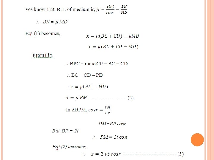
Interference in Thin Films due to reflected light Consider a transparent film of this t and refractive index is shown in figure. Let SA is incident ray, incident on upper surface of the film. It is partly reflected along AT and partly refracted along AB. At B part of it is reflected along BC and finally emerges out along CQ. To calculate the path difference between two rays AT and CQ, draw CN normal AT and AM normal to BC. Let i-is angle of incidence r- is angle of refraction. Also produce CB to meet AE produced at P. Hence APC = r.
The optical path difference is,
Eqn (3) is correct only when reflected light does not represent the correct path difference but only the apparent. It has been established on the basis of electromagnetic theory that, when light is reflected from the surface of an optically denser medium a phase change , equivalent to a path difference /2 occurs. Corrected path difference (1) If the path difference x = n , where n = 0, 1, 2, 3 …………etc. constructive interference takes place and the film appears bright.
(2) If the path difference x = (2 n+1) /2 , where n = 0, 1, 2, 3 …………etc. destructive interference takes place and the film appears dark. Here n is an integer only, therefore (n+1) is taken as n.
Interference in Thin Films due to reflected light Consider a transparent film of this t and refractive index is shown in figure. Let SA is incident ray, incident on upper surface of the film. At point A, it is partly refracted along AB. At B part of it is reflected along BC and partly refracted along BR. The ray BC after reflection at C, emerges along DQ. At B and C reflection takes place at the rarer medium. Hence no phase change occurs. Draw BM normal to CD and DN normal to BR. The optical path difference between the ray DQ and BR is given by,
(1) If the path difference x = n , where n = 0, 1, 2, 3 …………etc. constructive interference takes place and the film appears bright. (4) where n = 0, 1, 2, 3 ………… (2) If the path difference x = (2 n+1) /2 , where n = 0, 1, 2, 3 …………etc. destructive interference takes place and the film appears dark. (5) where n = 0, 1, 2, 3 …………
Fringes produced by a Wedge-Shaped Thin Film Consider two plane surfaces OA and OB inclined at an angle and enclosing a wedge-shaped air film. The thickness of the air film increases from O to A. When the air film is viewed with reflected monochromatic light, a system of equidistant interference fringes are observed which are parallel to the line of intersection of two surfaces. The interfering rays do not enter the eye parallel to each other but they appear to diverge from a point near the film. Suppose nth bright fringe occurs at Pn as shown in Fig. b. The thickness of the air film at Pn = Pn. Qn. Applying the relation for bright fringes, The optical path difference for reflected light is, where n = 0, 1, 2, 3 …………
As angle of incidence is small, cosr = 1. For air, = 1 and t = Pn. Qn (1) The next bright fringe (n+1) will occur at Pn+1, such that Subtracting eqn (1) from eqn (2)
The next bright fringe will occur at the point where thickness of the air film increases by /2. Suppose the (n+m)th bright fringe is at Pn+m. Then, there will be m bright fringes between Pn and P n+m such that (4) If the distance Qn+m. Qn = x Angle of inclination is, Therefore, the angle of inclination between OA and OB can be known. Here, x is the distance corresponding m fringes. The fringe width is,
Newton’s Ring: When a plano-convex lens of long focal length is placed on a plane glass plate, a thin film of air is enclosed between the lower surface of the lens and upper surface of the plate. The thickness of the air film is very small at the point of contact and gradually increases from the centre outwards. The fringes produced with monochromatic light are circular. The fringes are concentric circles, uniform in thickness with the point of contact as the centre.
The experimental set of Newton’s ring as shown in figure 1. Let S is a source of monochromatic light at the focus of the lens L 1. A horizontal beam of light falls on the glass plate B at 45 o. The glass plate B reflects a part of the incident light towards the air film enclosed by the lens L and the plane glass plate G. The reflected beam from the air film is viewed with a microscope. Interference takes place and dark and bright circular fringes are produced. This is due to the interference between the light reflected from the lower surface of the lens and upper surface of the glass plate G.
Newton’s Ring by reflected light Fig. (a) Fig. (b) Suppose the radius of the curvature of the lens is R and air film of thickness t is at a distance OQ = r, from the point of contact O. Here, the interference is due to reflected light. Therefore, the path difference for bright ring is Where n = 0, 1, 2, 3, …………
As, is small, cos = 1 and for air = 1. Above eqn becomes, (1) The path difference for dark ring is 2 t = n (2) Where n = 0, 1, 2, 3, ………… From Fig. (b), EP HE = OE (2 R-OE) But EP = HE = r , and OE = PQ = t r 2 = t ( 2 R – t) But 2 R – t 2 R r 2 = t. 2 R t = r 2/2 R Substituting value of t in eqn (1) and (2),
For bright ring, For dark ring, When n=0, the radius of the dark ring is zero and radius of bright ring is R/2. Therefore, the centre is dark. Alternately dark and bright rings are produced.
Determination of wavelength of sodium light using Newton’s Rings Suppose, the diameter on nth dark ring is Dn (1) Measure the diameter of the ring, it be Dn+m (n+m)th dark (2) Subtracting eqn(1) from eqn(2) By using this equation wavelength of sodium light is calculated.
Thank You!