SHREE SAD VIDYA MANDAL INSTITUTE OF TECHNOLOGY DEPARTMENT


- Slides: 60
SHREE SA’D VIDYA MANDAL INSTITUTE OF TECHNOLOGY DEPARTMENT OF CIVIL ENGINEERING
Subject: -Mechanics Of Solids Topic: -Shear stresses on
Presented by: Name Ø Arvindsai Enrollment no. 130454106002 Ø Dhaval Chavda 130454106001 Ø Fahim Patel 140453106005 Ø Navazhushen Patel 140453106008
Topics To Be Covered 1. 2. 3. 4. 5. 6. Shear Force Shear Stresses In Beams Horizontal Shear Stress Derivation Of Formula Shear Stress Distribution Diagram Numericals
Shear force �Any force which tries to shear-off the member, is termed as shear force. �Shear force is an unbalanced force, parallel to the cross-section, mostly vertical, but not always, either the right or left of the section.
Shear Stresses �To resist the shear force, the element will develop the resisting stresses, Which is known as Shear Stresses( ). Shear force S = Cross sectional A area
Example: �For the given figure if we want to calculate the . . �Then it will be Let shear force be S S =S/(bxd) d b
Shear Stresses In Beams �Shear stresses are usually maximum at the neutral axis of a beam (always if the thickness is constant or if thickness at neutral axis is minimum for the cross section, such as for I-beam or T-beam ), but zero at the top and bottom of the cross section as normal stresses are max/min. NA NA NA
�When a beam is subjected to a loading, both bending moments, M, and shear forces, V, act on the cross section. Let us consider a beam of rectangular cross section. We can reasonably assume that the shear stresses τ act parallel to the shear force V. b h V O z n m v
�Shear stresses on one side of an element are accompanied by shear stresses of equal magnitude acting on perpendicular faces of an element. Thus, there will be horizontal shear stresses between horizontal layers of the beam, as well as, Vertical shear stresses on the vertical cross section. n m
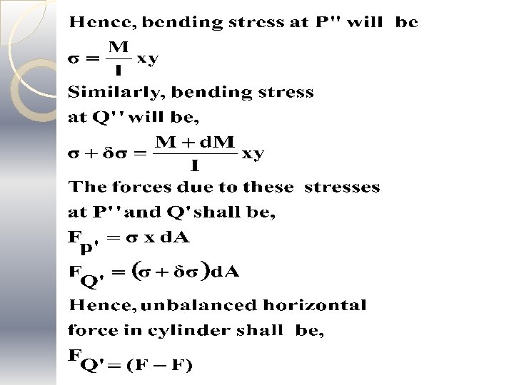
Horizontal Shear Stress �Horizontal shear stress occurs due to the variation in bending moment along the length of beam. �Let us assume two sections PP' and QQ', which are 'dx' distance apart, carrying bending moment and shear forces 'M and S' and 'M+ ∆M and S+ ∆S‘ respectively as shown in Fig.
�Let us consider an elemental cylinder P"Q" of area 'd. A' between section PP' and QQ' . This cylinder is at distance 'y' from neutral axis.
�This unbalanced horizontal force is resisted by the cylinder along its length in form of shear force. This shear force which acts along the surface of cylinder, parallel to the main axis of beam induces horizontal shear stress in beam.
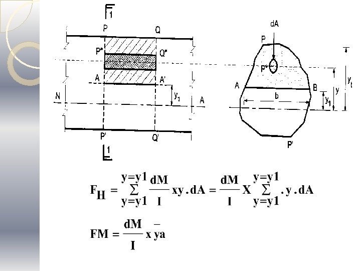
DERIVATION OF FORMULA: SHEAR STRESS DISTRIBUTION ACROSS BEAM SECTION �Let us consider section PP' and QQ' as previous. �Let us determine magnitude of horizontal shear stress at level 'AB' which is at distance YI form neutral axis. �The section above AA' can be assumed to be made up of numbers of elemental cylinder of area 'd. A'. Then total unbalance horizontal force at level of' AS' shall be the summation of unbalanced horizontal forces
�Here, y = distance of centroid of area above AB from neutral axis, And a= area of section above AB. �This horizontal shear shall be resisted by shear area ABA'B‘ parallel to the Neutral plane. The horizontal resisting area here distance of centroid of area above AB from neutral axis and a=area of section above AB. �Ah = AB x AA’=b x dx where ‘b’is width of section at AB.
�We know that shear force is defined as S=d. M/dx �Therefore, horizontal shear stress acting at any level across the cross sections.
SHEAR STRESS DISTRIBUTION DIAGRAM 1. Rectangular section NA max 2. Circular section NA max
3. Triangular section h/2 NA max avg 4. Hollow circular section NA max
5. Hollow Rectangular section NA max 6. “I” section NA max
7. “C” section max NA 8. “+” section NA max
9. “H” section max NA 10. “T” section NA max
Numericals
Rectangular section sum Example-1: Two wooden pieces of a section 100 mm X 100 mm glued to gather to for m a beam cross section 100 mm wide and 200 mm deep. If the allowable shear stress at glued joint is 0. 3 N/mm 2 what is the shear force the section carry ?
wooden piece 100 mm
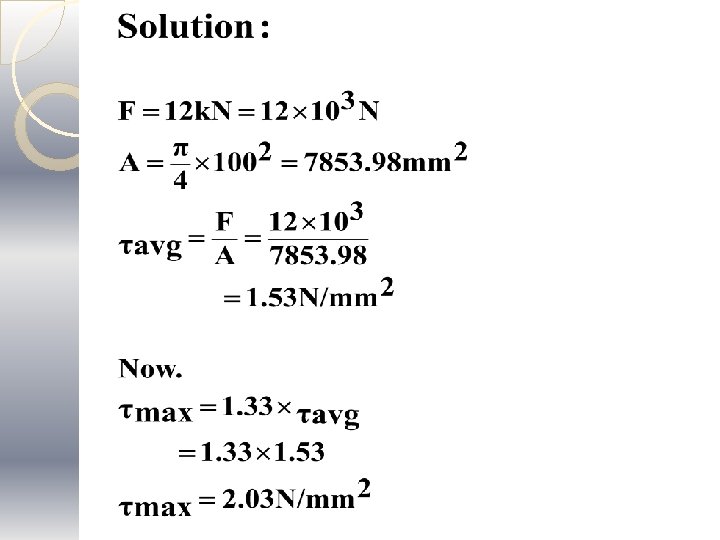
Circular section sum Example-2: A circular a beam of 100 mm Diameter is subjected to a Shear force of 12 k. N, calculate The value of maximum shear Stress and draw the variation of shear stress along the Depth of the beam.
D =100 mm NA
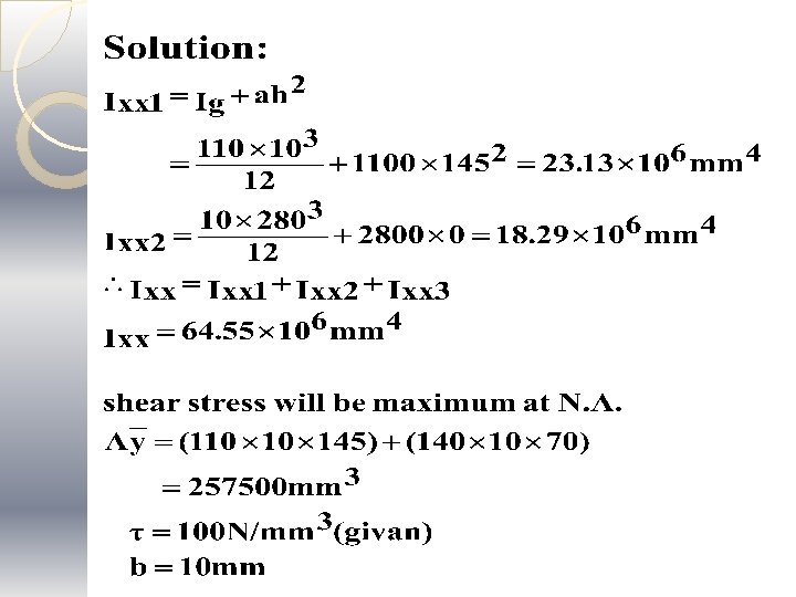
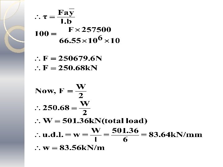
I section sum Example-3: A rolled steel joist of I section overall 300 mm deep X 100 mm wide has flange and web of 10 mm thickness. If permissible shear stress is limited to 100 N/mm 2, find the value of uniformly distributed load the section carry over a simply supported span of 6 m. �Sketch the shear stress distribution across the section giving value at the point of maximum shear force.
100 mm 10 NA 300 mm
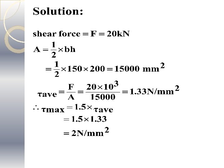
Triangular section sum Example-4: A beam of triangular section having base width 150 mm and height 200 mm is subjected to a shear force of 20 k. N the value of maximum shear stress and draw shear stress distribution diagram.
h/2 max=2 N/mm 2 200 mm 2/3. h NA avg=1. 33 N/mm 150 mm 2
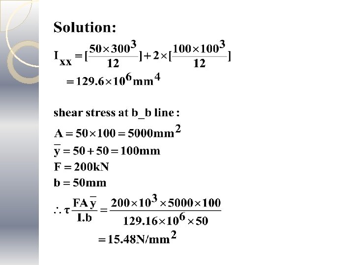
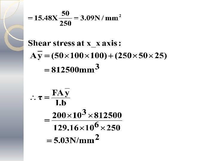
Cross section sum Example-5: FIG Shows a beam cross section subjected to shearing force of 200 k. N. Determine the shearing stress at neutral axis and at a-a level. Sketch the shear stress distribution across the section. 100 mm 50 mm 100 mm X 100 mm 50 mm
15. 48 N/mm 2 100 mm 50 mm X 100 mm NA 100 m m 100 mm 5. 03 N/mm 2 100 mm 50 mm 3. 09 N/mm 2
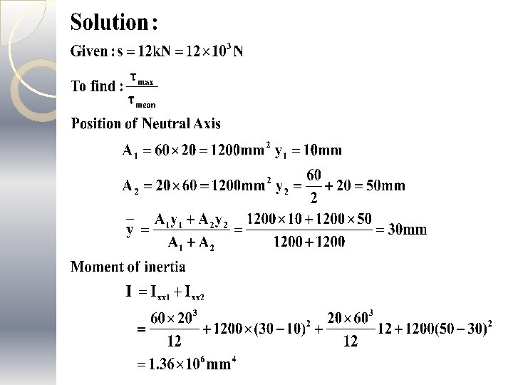
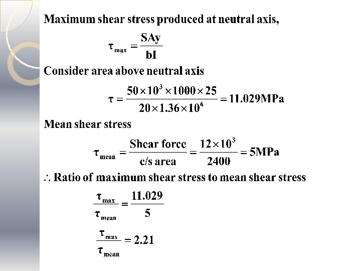
Inverted T section sum Example-6: Shows the cross section of a beam which is subjected to a vertical shearing force of 12 k. N. find the ratio the maximum shear stress to the mean shear stress. 20 mm 60 mm
max=11. 29 MPA 20 mm 60 mm NA 20 mm min avg=5 =2. 21 MPA
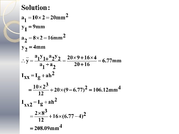
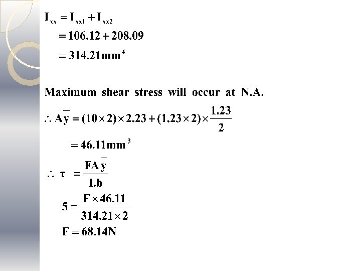
L section sum Example-7: An L section 10 mm X 2 mm show in the fig. is subjected to a shear force F. Find the value Of shear force F if max. shear stress developed is 5 N/mm 2.
10 mm 2 mm 3. 23 mm 10 mm 2 mm
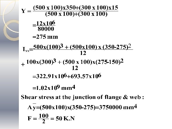
Tee section sum Example-8: A beam is having and subjected to load as shown in fig. Draw shear stress distribution diagram across the section at point of maximum shear force, indication value at all important points. 100 k. N A B 3 m 3 m
200 100 25 300 100 200
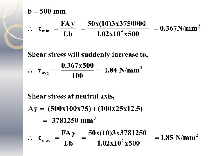
100 200 min=0. 367 N/mm 2 avg=1. 84 N/mm 2 100 25 NA 300 max=1. 85 N/mm 2
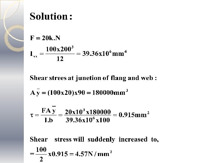
I section sum Example-9: Find the shear stress at the junction of the flange and web of an I section shown in fig. If it is subjected to a shear force of 20 k. N. 100 mm 200 mm
100 mm 20 mm NA 20 100 mm 200 mm
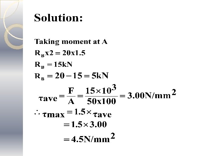
Rectangular section sum Example-10: A 50 mm x l 00 mm in depth rectangular section of a beam is s/s at the ends with 2 m span the beam is loaded with 20 k. N point load at o. 5 m from R. H. S. Calculate the maximum shearing stress in the beam. 20 k. N A B 0. 5 m RA 2. 0 m RB
50 mm 100 mm max=4. 5 N/mm 2 NA