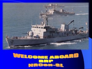
Ships Service Air System Components Compressors x 2


- Slides: 13

Ships Service Air System Components Compressors x 2 12 cfm@200 psi Staggered Auto Start One starts@165 psi the other @ 175 they both cut out@200 psi 460 v 3 phase

Components Compressor Discharge Piping and Filtration Notice just after the compressor outlet you see a Moisture control system. It consists of a reservoir with a Stainless Steel float that operates a needle and seat assembly. When full it lifts the needle and the moisture is forced out of the drain back to the oily-water tank via a hose.

Components Moisture Filter and Separator Immediately after the water drain reservoir is a Filter-Separator device with a flow style Metering gage. (Obvious When to change the filter) Notice this unit also drains back to the oily water tank.

Compone nts Compressed Air Isolation and Check Valve After the air treatment devices you will find the first two sets of Isolation Valves. These valves will be on the receiver's fill side piping. The Check Valve will keep the air from back flowing into the compressors. This configuration will be the same for both Compressor outlets.

Components Service Air Receivers (Tanks) x 2 Relief Valves at the top rear of the Tanks 220 psi The Receivers are rated at 200 gallons each. Note there is an Isolation Valve at the bottom of each of these receivers. One above the floor plates the other below. This Receiver Isolation Valve will be just behind where Fred is kneeling.

Components Distribution Piping Air Starting System Notice as the piping continues aft you’ll see two regulators. They control the pressures to the Air Starters. They will be set at 90 - 150 psi. Also these regulators can be isolated on either side.

Components Start Air Distribution After the regulators you'll see two larger Filter. Separator units. Again with a flow style Metering Gage. These service only the start air system. The unit closest inboard will be the one we use, as the other is more difficult to operate. (Standby Unit)

Components Air Start Distribution Two more items in this system to be aware of are (The Start Air Pressure gage) and the( Pressure relief valve) This pressure gage will tell you how HARD the starters will engage. The Relief valve works well as a air bleed off for the system if need be. The Gage is below the floor plates. 165 psi

Components Compressor Control Systems Compressor Control Panel Electronic Tank Condensation removal Controls. The water drains back to the oily water tank Air Pressure Sensors

Components Receiver Air Pressure Sensors and Gages Receiver’s respective pressure gages and sensors Notice below the gages there are independent system drain valves

Components General Service Air System This configuration is mounted on the forward ER bulkhead just to the outside of the compressors Isolation valves x 4 System air regulators with pressure gages Separator-Filter units that also drain back to the oily water tank Service air manifold to ships systems

Components General Service Air Relief Valve Service Air Manifold Gage 110 psi fwd ER Bulkhead

 Gardner denver blower division
 Sauer compressors
 Boilers are power absorbing device
 Fans blowers and compressors
 Bpcl industrial training
 Fans blowers and compressors
 Air higroskopis air kapiler dan air gravitasi
 Fantail of a ship
 O well for the fisherman's boy
 Maritime office in gdynia
 Elements of ships structure
 Ship general arrangement plan
 Mamimum gyroscopic couple,
 Xerxes bridge of ships
