Self Loading and Unloading Conveyor System Rylie Hanson


 • Consists purely of servos as")


 Two inch wide belts that are 23 inches long.")

 • • • Servos (8)-------------------------------$800 Gripper (2)------------------------------$30 Aluminum C channels for")


- Slides: 15
Self Loading and Unloading Conveyor System Rylie Hanson, Austin Noel, Nicole Ahrens ET 493 Spring 2016 Advisor: Mohammed Saadeh
Objective • To design and build a fully operational loading/unloading system • Loading/unloading system with two robotic arms, two conveyors and a rotating disc. • Improve our growing Engineering Technology Program • Comprised of different components for students to learn • Can be improved and modified over the years
Original Design • • • 1 large conveyor with help from Intralox. 3 in wide, 4 ft long conveyor. 2 SCARA Robots • 2 linear actuators attached to servo mounted rotating base. Rotating disk.
New Design: Arms • Articulate Robotic Arm (rotational-rotational) • Consists purely of servos as opposed to the original design which used linear actuators in conjunction with servos. • Frame is built using aluminum C channels • New SCARA Design (rotational-prismatic) • Built with two servos as well as a linear actuator that extends downwards with the end effector. Faster and more accurate • Servos can be accurately positioned. • Gripper coordinates can be calculated using servo feedback (forward kinematics) • Using inverse kinematics, servos can be configured to reach a desired position/orientation. •
The Arms
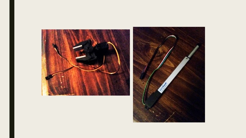
Linear Rail • • Aluminum X-rail 56 inches in length Moves a small aluminum platform attached to a belt by using a stepper motor. Platform is secured by the rivets of the rail to where it does not touch the rail itself, minimizing friction.
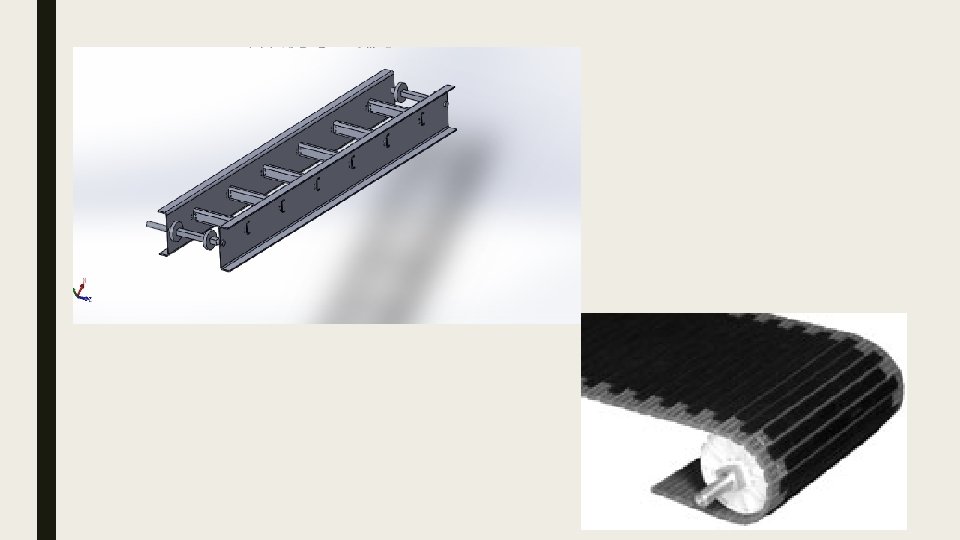
Continuous Belt Conveyor • (4) Two inch wide belts that are 23 inches long. • They will be connected together making the belt 92 inches long in total. • (6) Nine tooth sprockets that are 3. 75 inches in diameter. • The sprockets will be connected in pairs giving a total of three sprockets for the conveyor. Two on each end and one in the middle for support. • (4) 18 inch C-brackets that will be used for support for the belt so it doesn’t sag. • (4) Brackets for supporting the belt system on the table. Two on each side of belt.
Rotating Disk • • Gear motor mounted to a hub. Disk will rotate in increments according to the loading of the objects. Mounted bearings reduce uneven force on the motor. Disc will be crafted out of plywood while bearings and casing will be 3 d printed.
Budget (? ) • • • Servos (8)-------------------------------$800 Gripper (2)------------------------------$30 Aluminum C channels for frame of robots(4)----$80 Motors (rotating disc)----------------------$25 Wood for table---------------------------$80 Total-----------------------------------$1015
Tasks Completed • • Table for the system is built and stable. Linear motion pulley has been designed along with functioning motor using Adafruit Motor Shield. Robotic arms have been assembled and have been successfully tested for functionality using Arduino in conjunction with a power supply. Parts just arrived for the continuous belt conveyor system and is ready for assembly
Deliverables • • • Assemble rotating disk and belt conveyor. Attach end effectors to both arms. Wiring of loading and unloading assembly with PLC controls.
Timeline • • d September • Assemble rotating disk and belt conveyor. • 3 D print casing for SCARA linear actuator • Attach the end effectors of both arms. October • Attach parts to table. • Begin wiring and programming of individual components. November • Coordination and timing of individual components to form a fully functional and operating system. December • Testing and debugging. • Presentation
Questions? ?