PERFORMANCE DEGRADATION OF DIELECTIRIC RADOME COVERED ANTENNAS 1
- Slides: 12
PERFORMANCE DEGRADATION OF DIELECTIRIC RADOME COVERED ANTENNAS 1
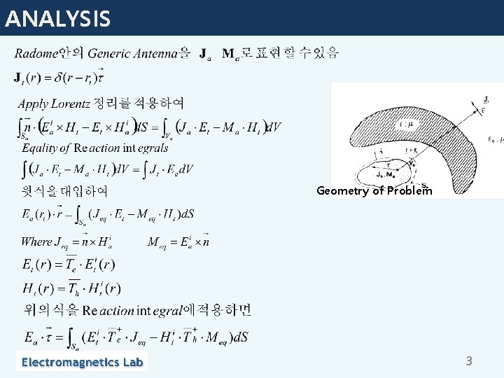
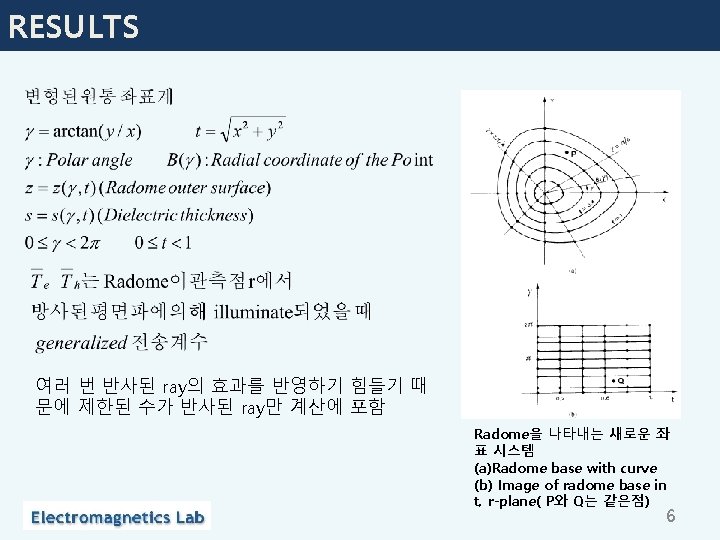
ANALYSIS Geometry of Problem 3
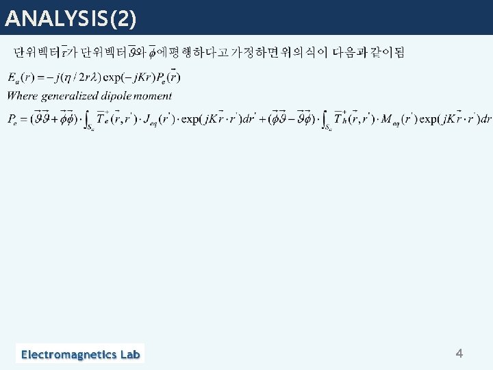
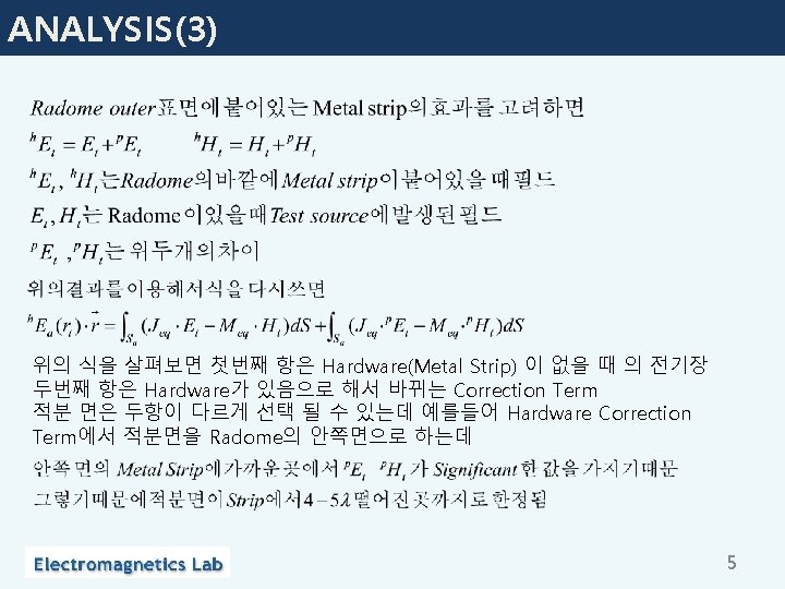
ANALYSIS(2) 4
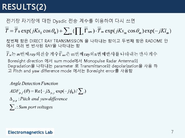
RESULTS(2) 전기장 자기장에 대한 Dyadic 전송 계수를 이용하여 다시 쓰면 첫번째 항은 DIRECT RAY TRANSMISSION 을 나타내는 항이고 두번째 항은 RADOME 안 에서 여러 번 반사된 RAY을 나타내는 항 Boresight direction 에서 sum mode에서 Monopulse Radar Antenna의 Degradation을 나타내는 parameter 로 Transmittance와 depolarization을 사용 하 고 Pitch and yaw difference mode 에서는 Boresight error를 사용함 7
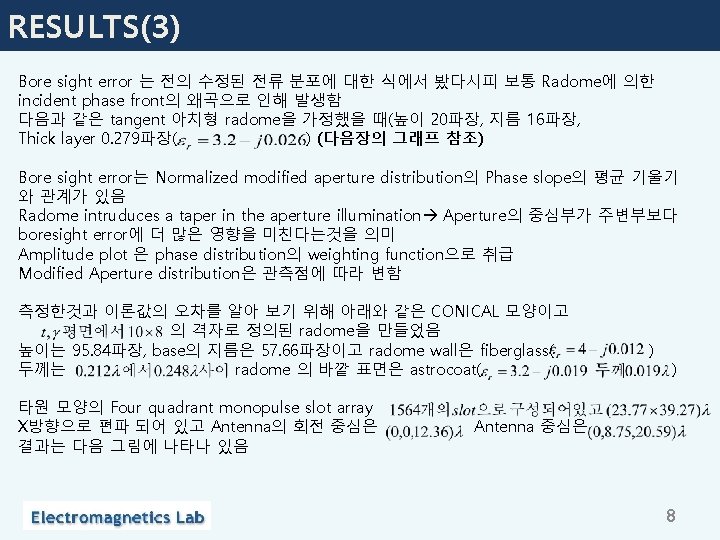
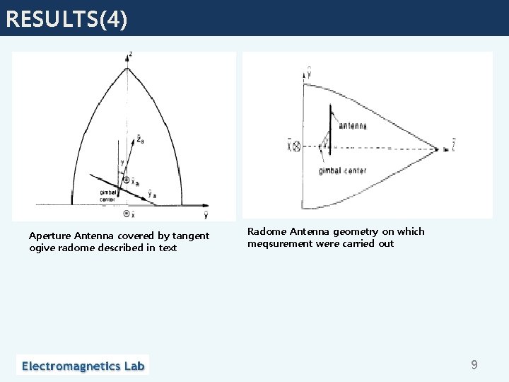
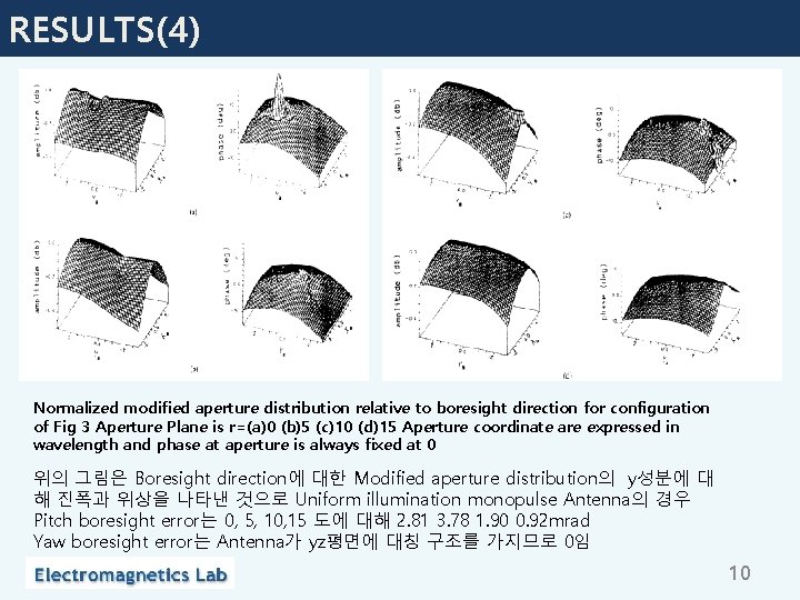
RESULTS(3) Bore sight error 는 전의 수정된 전류 분포에 대한 식에서 봤다시피 보통 Radome에 의한 incident phase front의 왜곡으로 인해 발생함 다음과 같은 tangent 아치형 radome을 가정했을 때(높이 20파장, 지름 16파장, Thick layer 0. 279파장( ) (다음장의 그래프 참조) Bore sight error는 Normalized modified aperture distribution의 Phase slope의 평균 기울기 와 관계가 있음 Radome intruduces a taper in the aperture illumination Aperture의 중심부가 주변부보다 boresight error에 더 많은 영향을 미친다는것을 의미 Amplitude plot 은 phase distribution의 weighting function으로 취급 Modified Aperture distribution은 관측점에 따라 변함 측정한것과 이론값의 오차를 알아 보기 위해 아래와 같은 CONICAL 모양이고 의 격자로 정의된 radome을 만들었음 높이는 95. 84파장, base의 지름은 57. 66파장이고 radome wall은 fiberglass( 두께는 radome 의 바깥 표면은 astrocoat( 타원 모양의 Four quadrant monopulse slot array X방향으로 편파 되어 있고 Antenna의 회전 중심은 결과는 다음 그림에 나타나 있음 ) ) Antenna 중심은 8
RESULTS(4) Aperture Antenna covered by tangent ogive radome described in text Radome Antenna geometry on which meqsurement were carried out 9
RESULTS(4) Normalized modified aperture distribution relative to boresight direction for configuration of Fig 3 Aperture Plane is r=(a)0 (b)5 (c)10 (d)15 Aperture coordinate are expressed in wavelength and phase at aperture is always fixed at 0 위의 그림은 Boresight direction에 대한 Modified aperture distribution의 y성분에 대 해 진폭과 위상을 나타낸 것으로 Uniform illumination monopulse Antenna의 경우 Pitch boresight error는 0, 5, 10, 15 도에 대해 2. 81 3. 78 1. 90 0. 92 mrad Yaw boresight error는 Antenna가 yz평면에 대칭 구조를 가지므로 0임 10
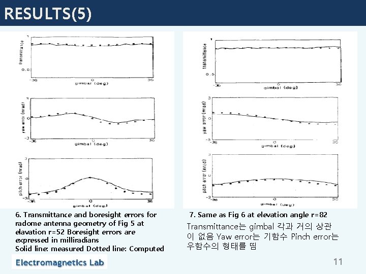
RESULTS(5) 6. Transmittance and boresight errors for radome antenna geometry of Fig 5 at elavation r=52 Boresight errors are expressed in milliradians Solid line: measured Dotted line: Computed 7. Same as Fig 6 at elevation angle r=82 Transmittance는 gimbal 각과 거의 상관 이 없음 Yaw error는 기함수 Pinch error는 우함수의 형태를 띰 11
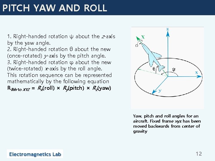
PITCH YAW AND ROLL 1. Right-handed rotation ψ about the z-axis by the yaw angle. 2. Right-handed rotation θ about the new (once-rotated) y-axis by the pitch angle. 3. Right-handed rotation φ about the new (twice-rotated) x-axis by the roll angle. This rotation sequence can be represented mathematically by the following equation Rlhlv to XYZ = Rx(roll) × Ry(pitch) × Rz(yaw) Yaw, pitch and roll angles for an aircraft. Fixed frame xyz has been moved backwards from center of gravity 12