Optical Position Sensor for the VWS Improvements and


- Slides: 10
Optical Position Sensor for the VWS Improvements and optimization Jose Luis Sirvent Jonathan Emery Student Meeting 12– February -2012
1. 850 nm VS 1310 nm � Free Space behavior of light: ◦ Transmission & Reflection
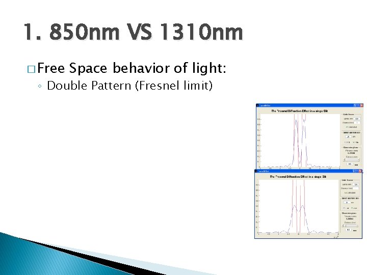
1. 850 nm VS 1310 nm � Free Space behavior of light: ◦ Double Pattern (Fresnel limit)
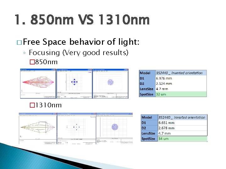
1. 850 nm VS 1310 nm � Free Space behavior of light: ◦ Focusing (Very good results) � 850 nm � 1310 nm
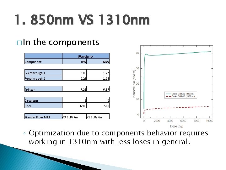
1. 850 nm VS 1310 nm � In the components Wavelenth Component 850 1300 Feedthrough 1 2. 08 1. 27 Feedthrough 2 2. 14 1. 06 Splitter 7. 23 6. 57 3 2 1700 500 Circulator Price Standar Fiber MM <3. 5 d. B/Km <1. 5 d. B/Km ◦ Optimization due to components behavior requires working in 1310 nm with less loses in general.
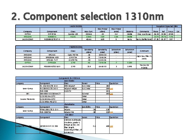
2. Component selection 1310 nm LASER DIODES Class Ga. AIAs LED VCSEC Max Curr. 100 m. A 12 m. A 45 m. A Max Power (d. Bm) -10 1. 59 6. 98 Max Power (m. W) 0. 1 1. 44 5 Sensibility (m. W) 3. 98 E-03 7. 94 E-04 5. 01 E-04 7. 94 E-05 Saturation (d. Bm) -7 6. 46 E-03 3 Company OPTEK KYOSEMI LASER COMP Component OPF 372 A KLD 085 VC PL 85 B 002 ST 83 -T-0 Company Component Class KYOSEMI OPTEK KPGX 1 G KPIX 150 M-H 33 KPIXAIG-T-ST OPF 562 A Ga. As PD-TIA Si APD-TIA Si PD Sensibility (d. Bm) -24 -31 -33 -41 LASER COMP PDSIU 500 ST 83 -W-0 Si PD -21. 9 PHOTODIODES Company Laser Comp BFI Source Photonics Company Laser Company Compo. Tron Gmb. H Components for 1310 nm Laser diodes Component Class Power Price PL 13 U 002 ST 8 3 -0 -I DFB In. Ga. As. P 0. 1 -2 m. W PL 13 B 002 ST 8 3 -0 -0 In. Ga. As. P MQW 0. 1 -2 m. W PLD-1315 ELED-TX 300 -0050 -02 1310 nm ST 0. 8 m. W C-13 -001 -RA-SST 2 2 m. W C-13 -002 -RA-SST 2 2 m. W C-13 -DFBA-PB-SST 2 2 m. W Photodiodes Component Class Sensibility Price PTIN S 155 ST 8 3 -O-V In. Ga. As -36 PLD-2315 TM In. Ga. As PIN -38 Circulator Component Class Losses Price 1310 nm multimode circulator, grade P, 900μm jacket, 1 m MPIOC 3 13 P 2 1 2 55 2. 6 fiber length, 62, 5/125μm fiber, ST connectors Quotation 280 159 Link 182 150 Link Quotation 129 118 Link Quotation 605 Link Stability Stable Noisy Comments Fine, Low Power Noisy (Reflections) Saturation Comment (m. W) High-Pass filter F> 1 Mhz 0. 200 TIA Circ OK 1. 995 F<2 Mhz Reception Expected d. Bm Trans Ref Focus -34. 33 -32. 35 -19. 55 -22. 74 -20. 76 -7. 96 -17. 35 -15. 37 -2. 57 Col -
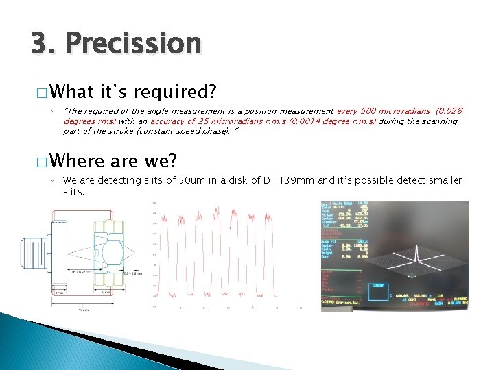
3. Precission � What ◦ it’s required? “The required of the angle measurement is a position measurement every 500 microradians (0. 028 degrees rms) with an accuracy of 25 microradians r. m. s (0. 0014 degree r. m. s) during the scanning part of the stroke (constant speed phase). “ � Where are we? ◦ We are detecting slits of 50 um in a disk of D=139 mm and it’s possible detect smaller slits.
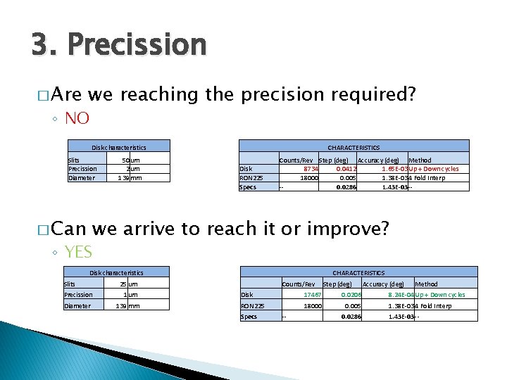
3. Precission � Are we reaching the precision required? ◦ NO Disk characteristics Slits Precission Diameter � Can 50 um 2 um 139 mm CHARACTERISTICS Disk RON 225 Specs Counts/Rev Step (deg) Accuracy (deg) Method 8734 0. 0412 1. 65 E-03 Up + Down cycles 18000 0. 005 1. 38 E-03 4 Fold Interp -0. 0286 1. 43 E-03 -- we arrive to reach it or improve? ◦ YES Disk characteristics Slits 25 um Precission 1 um Diameter 139 mm CHARACTERISTICS Counts/Rev Step (deg) Disk 17467 0. 0206 RON 225 18000 0. 005 Specs -- 0. 0286 Accuracy (deg) Method 8. 24 E-04 Up + Down cycles 1. 38 E-03 4 Fold Interp 1. 43 E-03 --
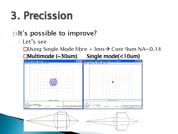
3. Precission � It’s possible to improve? ◦ Let’s see �Using Single Mode fibre + lens Core 9 um NA=0. 14 �Multimode (~30 um) Single mode(<10 um)
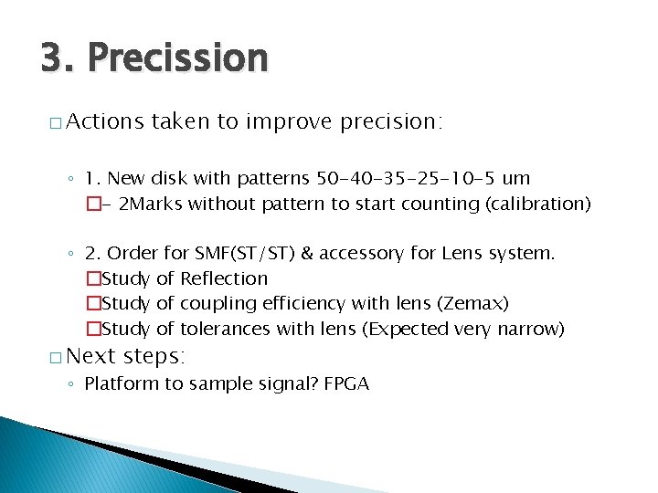
3. Precission � Actions taken to improve precision: ◦ 1. New disk with patterns 50 -40 -35 -25 -10 -5 um �- 2 Marks without pattern to start counting (calibration) ◦ 2. Order for SMF(ST/ST) & accessory for Lens system. �Study of Reflection �Study of coupling efficiency with lens (Zemax) �Study of tolerances with lens (Expected very narrow) � Next steps: ◦ Platform to sample signal? FPGA