Ohms Law and Resistors in Series and in


- Slides: 14

Ohm's Law and Resistors in Series and in Parallel Presented by Mahmud Abdur. Rahman & Nazim Uddin Physics 2. 3 honor Class DR. Roman Kezerashvili

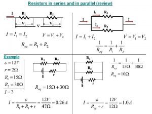
Objectives: 1. Verify law by observing the dependence of the electric current as a function of voltage and as a function of resistance. • 2. Determine the equivalent resistance of series and parallel combination of resistors and compare the results with theoretical predictions. • 3. Study currents flow and voltages in series and parallel circuits.

Equipment • 1 Resistance box • 2. Digital Multmeter • 3. DC power supply with adjustable voltage (0 -20 V) • 4. Resistors board • 5. Connecting wires • 6. Switch

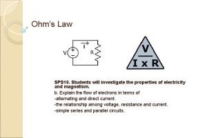
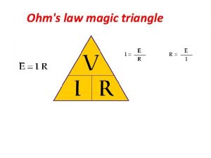
Theory What is the Ohm’s Law • Ohm’s law States that current through a resistor is directly proportional to the applied voltage V and inversely proportional to the resistance R of the resistance • Ohm’s law is not a fundamental law of nature • An empirical relationship that is valid for certain material • at constant temperature Electric current I=Q/T Ohm’s Law I=V/R

Procedure • Part 1 • 1. Investigate the variation of the current with potential difference when the resistance is constant • 2. Investigate the variation of the current with resistance when the voltage is constant. • Part II • 1. Resistors in series • 2. Resistors in Parallel

Ohm’s Law( The relationship among current, voltage and resistance) Resistors in Series Resistors in Parallel Data: » Table 1. The Voltage Dependence of Current (Constant resistance) • Power supply , V • Voltage V, R 1= 1000 R 2= 1200 V Current I, A Voltage V, V • 4 4. 02 0. 0040 4. 02 0. 0033 • 5 5. 02 0. 0049 5. 02 0. 0041 • 6 6. 02 0. 0060 6. 03 0. 0049 • 7 7. 02 0. 0070 7. 04 0. 0058 • 8 8. 01 0. 0079 8. 01 0. 0066 • 9 9. 01 0. 0090 9. 00 0. 0074 10 10. 03 0. 0099 10. 02 0. 0082

Data • Resistance R, 1/R, -1 • 700 0. 00143 • 800 0. 00125 0. 01490 • 900 0. 00111 0. 01320 • 1000 0. 00100 0. 01190 • 1100 0. 00091 0. 01084 • 200 0. 00083 0. 00994 Current I, A 0. 01700 Voltage Power supply V, V=12 V from Slope, V 11. 874 %Difference 1. 06%

» Table 3. Resistors in Series Continuation • I = 0. 0024 A, V = 12 V, • Resistors Current I, A Voltage V, V Resistance R, • RA 0. 0024 8. 74 3620 • RB 0. 0024 2. 63 1090 • RC 0. 0024 0. 57 230 R = 4950 Equivalent resistance from equation (9) R = 4940 ; % difference = 0. 20% Total voltage from equation (5) % difference = 0. 50% V = 11. 94 V; – Table 4. Resistors in Parallel • I = 0. 032 A, • Resistors Current I, A Voltage V, V Resistance R, • RA 0. 0018 6 3620 • RB 0. 0054 6 1090 • RC 0. 026 6 230 V = 6 V, R = 185. 6

GRAPH

Graph 2

Calculation and Analysis: 1. Use data from Table 1 and plot a graph of the current I us the voltage V for both values of the resistance. Determine the slope of the graph. From the slope of the graph find the resistance using » R=1/slope • and compare it to the actual value of resistance by calculating a percent difference. – 2. Use data from Table 2 and plot a graph of the current I versus the 1/R. Determine the slope of the graph. Compare the slope of the graph with the output voltage of power supply by computing a percent difference. – 3. Resistors in series. – Using the resistors value compute the equivalent resistance R of the circuit by using equation (9). Compare this value with your experimental measurement by finding a percent difference. – Using the measured voltages compute the total voltage V by using equation (5). Compare this value with your experimental measurement by finding a percent difference.

Continue Calculations

Continue Calculations

• According to the experiment we observed that the electric current through a resistor is directly proportional to the applied voltage and inversely proportional to the resistance of the resistor and verified Ohm’s law. • We also observed the difference between series and parallel connections. I LOVE PHYSICS THANKS TO PROFESSOR DR. ROMAN FOR MAKING PHYSICS SO ENJOYABLE
 Resistors in series and parallel
 Resistors in series and parallel equations
 Types of circuits and ohms law
 Ohms law resistance
 Point form of ohms law
 Ohms law resistance
 Ohm's law states that *
 Ohms law magic triangle
 Watts law
 Ohms law emf
 Electric circuit definition
 Introduction of ohm's law
 Worksheet circuits and ohm's law answer key
 A certain light bulb has a tungsten filament
 Ohms law derivation
