Measurement of DC resistivity of new quasionedimensional conducting


2 aka “TCP” New Q 1 D platinate: TCP • Cs 4[Pt(CN)4](CF 3 SO 3)2 aka “TCP”](https://slidetodoc.com/presentation_image_h/97ffaf6723e2ee13ec0c30d4846380a0/image-5.jpg)


- Slides: 16

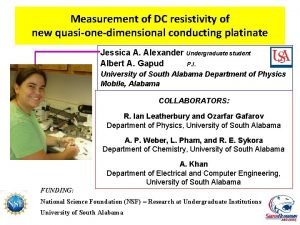
Measurement of DC resistivity of new quasi-one-dimensional conducting platinate Jessica A. Alexander Undergraduate student Albert A. Gapud P. I. University of South Alabama Department of Physics Mobile, Alabama COLLABORATORS: R. Ian Leatherbury and Ozarfar Gafarov Department of Physics, University of South Alabama A. P. Weber, L. Pham, and R. E. Sykora Department of Chemistry, University of South Alabama A. Khan Department of Electrical and Computer Engineering, University of South Alabama FUNDING: National Science Foundation (NSF) – Research at Undergraduate Institutions University of South Alabama

Measurement of DC resistivity of new quasi-one-dimensional conducting platinate Jessica A. Alexander Undergraduate student Albert A. Gapud P. I. University of South Alabama Department of Physics Mobile, Alabama COLLABORATORS: R. Ian Leatherbury and Ozarfar Gafarov Department of Physics, University of South Alabama A. P. Weber, L. Pham, and R. E. Sykora Department of Chemistry, University of South Alabama A. Khan Department of Electrical and Computer Engineering, University of South Alabama FUNDING: National Science Foundation (NSF) – Research at Undergraduate Institutions University of South Alabama

Quasi-One-Dimensional Conductors (Q 1 D) • Restricted geometry: current confined to chain of metal ions/atoms • Peierls Transition: from conductor to insulator, due to lattice distortion – New periodicity, a --> 2 a – corresponds to k = 2 k. F – Elastic energy balanced by coulomb interaction – energy gap at k|| = k. F from Gruner, Reviews of Modern Physics, Vol. 60, No. 4, Oct 1988

Q 1 D platinates, KCP Platinates: parallel chains of Pt along crystal symmetry axis K 2 Pt(CN)4 Br 0. 33. H 20 aka “KCP” • extensively studied (1970 s) • Each Pt chain ringed by 4 CN • Adjacent Pt planes rotated 45 o • Pt-Pt spacing: • • Longitudinal – along chain: 2. 89 Å Transverse – between chains: 9. 88 Å • 4 H 2 O rings each Pt-CN plane • K, Br separate Pt-CN-H 2 O complexes From: Toombs, Physics Reports 40, No. 3(1978)181.
2 aka “TCP”](https://slidetodoc.com/presentation_image_h/97ffaf6723e2ee13ec0c30d4846380a0/image-5.jpg)
New Q 1 D platinate: TCP • Cs 4[Pt(CN)4](CF 3 SO 3)2 aka “TCP” • Pt-CN complexes: like KCP CN Pt CN • Pt-Pt spacing (room temp): – Longitudinal: 3. 03 Å (5% longer) – Transverse: 13. 61 Å (38% farther) • Cs instead of H 2 O • Triflates (CF 3 SO 3 -) instead of K, Br

Our Study: DC resistivity of TCP KCP: Conductivity vs T • High anisotropy - Transverse ~ 105 lower • Peierls transition temperature not observed (above room temperature? ): already semiconducting/insulating • DC ρ(T): increases with cooling OBJECTIVE: TCP: Measure ρ(T); compare to KCP • Effect of longer Pt-Pt spacings = ? From: Toombs, Physics Reports 40, No. 3(1978)181.

Experimental Details: TCP samples • precipitate from solution • bright metallic red in color • small dimensions: – approximately 2 -5 mm in length – less than 1 mm wide – less than 0. 5 mm thick • extremely fragile – a “Krogmann salt” – must be handled indirectly • opted for 2 -point contact – Contact R << sample R • (contacts tested on Cu dummy)

Experimental Details: Mounting Problem: Contact with Sample Solution: Sputtered Au • hydroscopic: liquid layer on the surface of the TCP – Carbon paint contact: V increase (charging) – Sputtered Au : enough energy for better contact for carbon paint, prevent moisture • • brass foil teflon tape masking: sample set in the folds of teflon tape; covered w/ brass strip Better contact: V stable (no charging) TCP sample glass slide DC Sputtering System Samples Prepared for DC Sputtering

Experimental Details: Mounting Problem: Thermal Shock • m mounts attempted Various • Initial, anchored mount: sapphire coated w/ Au, sample across gap in Au • Sample breakage w/ thermal cycling • Thermal expansion/contraction coefficient significant Freund, J. Appl. Cryst. 7, 631 (1974) • “Friction mount”: sample across foils on vacuum grease • Stability + more freedom for thermal expansion/contraction • “Spring mount”: sample leads are slack • Stability + more freedom for thermal expansion/contraction • Sample on teflon-tape surface • Pt wire C-painted “dumbbells”

Experimental Details: Mounting Problem: Thermal Shock • m Solution: “Guitar Mount” with Pt Wires • • Initial, anchored mount: - Sample breakage - Disjointed R(T) from Coleman, Review of Scientific Instruments – August 1975 G 10 base w/ a gap in the middle Suspension wires – – – • • • sample laid each wire across G 10 gap separation distance tailored to sample taped to the G 10 at each side of the gap slack used copper wire at first; switched to platinum wires for less mass & tension sample across the wires, C paint contact soldered wires to fixed current leads SLOW cooling and warming • Max 3 K/min platinum wire tape G 10

Results: • CRITERIA: – Smooth R(T) • good contact, no thermal shock – Reversible with temperature • TCP: more insulating than KCP – R ~ 107 Ω – σ|| ~ 10 -5 (Ωcm)-1 Compared to KCP: • Average ~ 105 times smaller • T variation ~ 103 less • Anomalous peak in R(T) – T > 200 K: monotonic increase w/ cooling, like KCP – T ~ 170 K: saturate, then decrease TCP 13 Guitar

Further study: not like KCP Structural transition below 200 K: towards KCPlike spacing? • Cryogenic XRD shows lattice contraction w/ cooling – 210 K: • Longitudinal: decrease 1. 15% • Transverse: decrease 0. 35% – (Lower temperatures: ongoing) – Peak: Effect dominated by 3 D ordering (inter-chain) ? • • T > 200 K: Different orbital sharing for Pt-Pt? SQUID magnetometry: no response Want: specific heat, pressure effects, … May be consistent with results of NMR study (next talk)

Spare slides follow

Experimental Details: DC transport Settings: Dewar, minimum temp = 4. 2 K meters and power supply computer and interface • apply current, measure voltage – set based on room temperature resistance of the sample – Both directions, to eliminate offsets • temperature control – Indirect cool w/ liquid nitrogen – Slow cool / warm • < 3 K/min student 9 -T, 60 -A DC Transport System at USA-Physics

Results: “Friction Mount”: showed effect of compression/tension? carbon paint platinum wire • Intermediate between “guitar” and anchored: residual restriction to thermal contraction/expansion sample G 10 vacuum grease brass foils copper wire Figure of the Friction Mount – base : molded G 10 – four brass foil strips, each mounted on vacuum grease – Sample mounted on inner foils, C paint – Inner foils connected to outer foils w/ slack Pt wire, C paint – current leads: copper wires connected to outer foils w/ C paint

Results: “Friction Mount”: showed effect of compression/tension? • m TCP 6 Friction • Warming (red): thermal expansion may be suppressed by friction mount: equivalent to longitudinal compression • compression may be responsible for earlier thermal shock breakages • mount: compression may be weak enough to preserve sample but significant enough to affect electrical properties • should increase with T • KCP R(T) decreases with compression. TCP : reverse result! • 170 K: dip instead of peak • <170 K: like KCP • >170 K: compression increases R?
 Measurement of dc resistivity
 Dimensions of resistance
 Resistivity vs resistance
 Resistivity log
 Resistivity depends on
 Tournnet
 Cz silicon wafer with high resistivity
 Factors affecting resistivity of rocks
 Resistivity
 Unit of resistivity
 Copper conductivity s/m
 Resistivity unit
 Resistivity by four probe method
 Spitzer resistivity
 Rics rules of measurement
 New rules of measurement
 Measurement standards laboratory
