Manchester Christmas Meeting Michael Sullivan Wakeeld and Impedance


- Slides: 17
Manchester Christmas Meeting Michael Sullivan Wakefield and Impedance Studies with Ultra-Relativistic Beams on CLARA and UK FEL 1
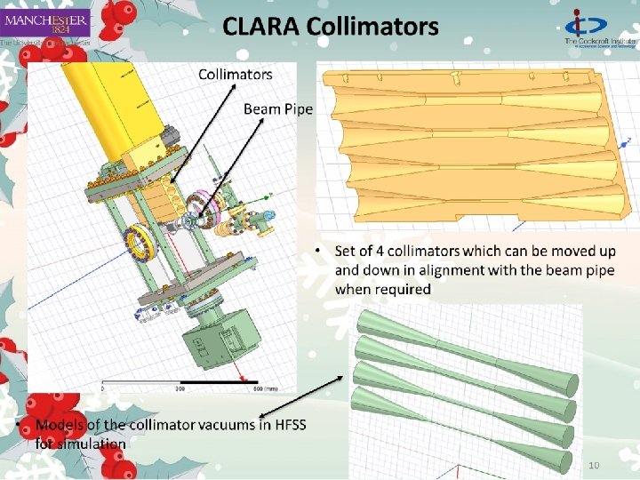
Overview • My Ph. D concerns characterising the wakefields produced by the electron beam in various components of The Compact Linear Accelerator for Research and Application (CLARA) system. To this date: • Wakefields produced in the S-band CLARA Linac 01 have been investigated using Circuit Models. • CLARA collimator impedances have also been investigated via a Parabolic form of Maxwells Equations and the wakefield codes ECHO 2 D and ABCI. 2
Motivation • Wakefields in accelerators are harmful as they can degrade the quality of the beam, as well as kick the beam into the wall. • CLARA is designed to test new and upcoming regimes of FEL operations and will be used for research and industrial experiments. • This will not be possible if the wakefields limit the quality of the beam. Disadvantages • Beam instabilities • Beam energy loss • Heating of components • Increased energy spread of bunch • Emittance growth/beam size Figure 1. A schematic diagram of the CLARA layout. 3
What are Wakefields? Types of Wakefields • Short-range and Long-range • Longitudinal and Transverse • Geometrical wakefields • Resistive wall wakefields. 4
CLARA Linac 01 TE 110 TM 110 Figure 4. Dipole dispersion of several CLARA cells. Figure 3. A 90 degree slice of cell 31 of Linac 01. Figure 5. Monopole dispersion of several CLARA cells. 5
Coupled and Uncoupled Wakes The uncoupled wakefield: The single chain circuit model: Figure 8. A depiction of the single chain circuit model used to couple cells to their nearest neighbours. The double chain circuit model: 6
Coupled and Uncoupled Wakes Figure 9. The results of the uncoupled, single and double chain circuit models for the linearly distributed CLARA Linac 01 structure. Shown are the distribution of the frequencies (top left), the kick factor (bottom left), the product of the kick and distribution (top right) and the envelope of the wake (bottom right. ) 7
Parabolic Equation Method • Existence of a small parameter in numerical methods can lead to long computation times or large amount of computational power needed: • Very short bunches • Small tapering angle • Model beam as a propagating current: • Longitudinal impedance: • Split up the E field into the field from the source and the fields generated from image charges and currents in the walls: • Source field “Vacuum” field Important advantage of this is by transforming , the wavenumber and the associated frequency are eliminated from the equation!
Parabolic Equation Method Stupakov Geometry
Heaviside Approximation Real Field Imaginary Field
Heaviside Approximation • Solving the PE with the Piecewise structure region by region • Solving the PE using Heaviside function approximation:
XARA Future Upgrade • X-band Accelerator for Research and Applications • The 4 th CLARA linac is replaced by an X-band accelerating section to reach 1 Ge. V • Novel FEL technology • An EUV/soft x-ray FEL facility for ultra fast chemistry and biology, and a centre of accelerator R&D.
XARA Future Upgrade Full Energy Beam Exploitation • Experimental user station: • • • Nominally at 250 Me. V/c – up to ~600 -700 Me. V/c on XARA Sub-100 fs electron bunches at 250 p. C High peak-currents > 4 k. A • Experiments: • Wakefield Accelerator experiments: • Structure WFA (dielectric, with mask in arc for 2 bunch) • Beam-driven PWFA • VHEE • Strong links with Christie Hospital and Manchester University
XARA Future Upgrade X-band linac • Based on Eu. PRAXIA@SPARC_LAB/Compact. Light/Electrons into SPS RF module • 4 x 1 m 80 MV/m x-band cavities per module • 3 modules M. Diomede et al 2014, NIMA Vol. 909 • Due to the short bunch lengths, short range wake-fields in the X-band cavities have a strong impact on the beam dynamics.
Thank you! Merry Christmas!
Appendix Table A. Details of characteristic cells of the CLARA Linac 01 structure. From left to right: cell number, iris radius, equator radius, synchronous frequency, synchronous kick factor, resonator frequency, coupling factor.