Lecture 16 Todays topics MARIE Instruction Decoding and
- Slides: 23
Lecture 16 • Today’s topics: – MARIE Instruction Decoding and Control – Hardwired control – Micro-programmed control 1
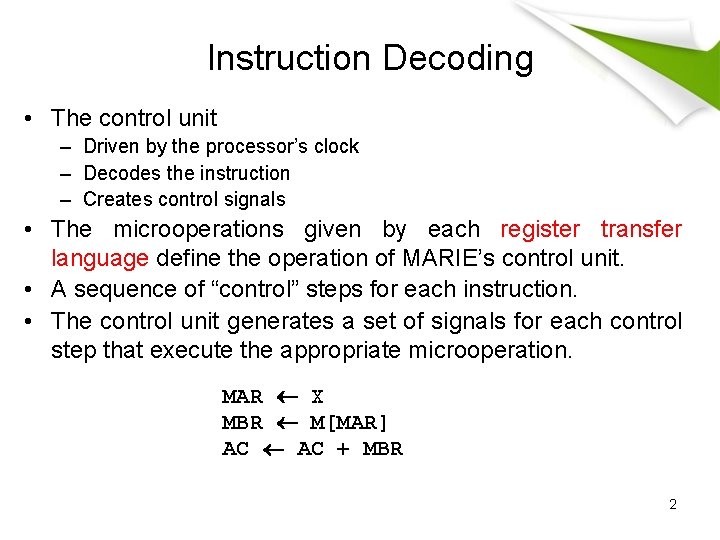
Instruction Decoding • The control unit – Driven by the processor’s clock – Decodes the instruction – Creates control signals • The microoperations given by each register transfer language define the operation of MARIE’s control unit. • A sequence of “control” steps for each instruction. • The control unit generates a set of signals for each control step that execute the appropriate microoperation. MAR X MBR M[MAR] AC + MBR 2
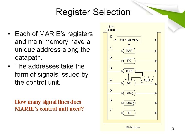
Register Selection • Each of MARIE’s registers and main memory have a unique address along the datapath. • The addresses take the form of signals issued by the control unit. How many signal lines does MARIE’s control unit need? 3
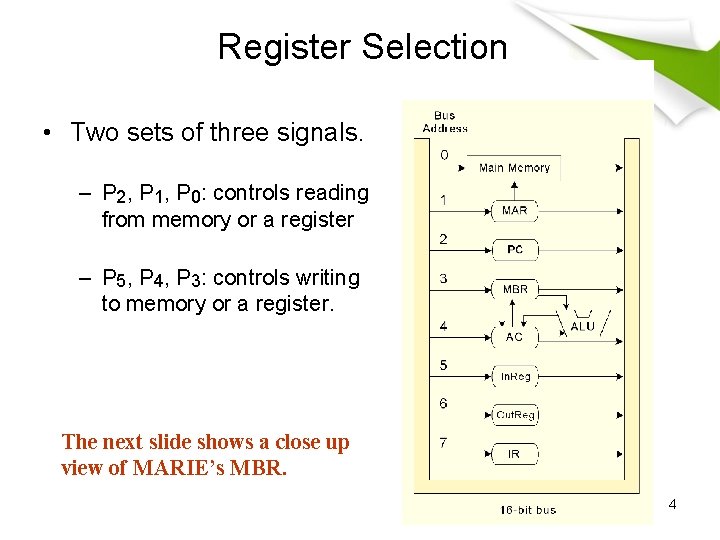
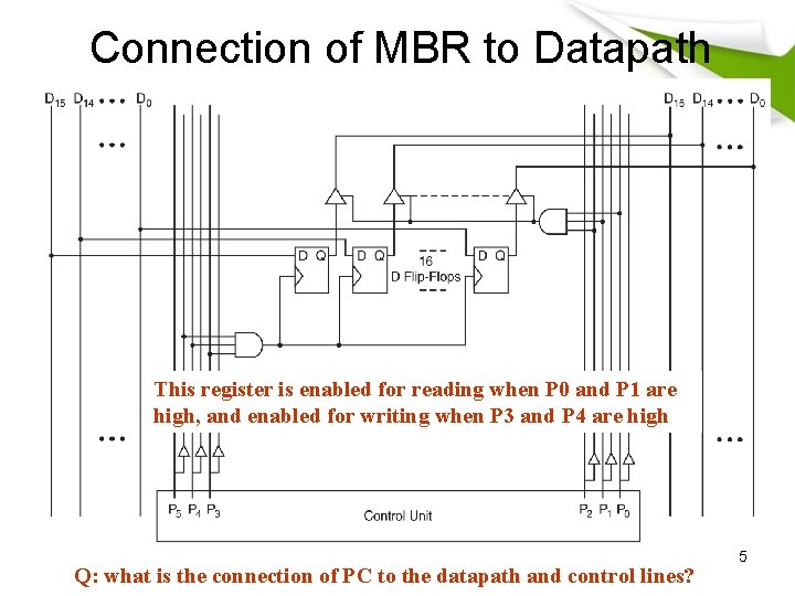
Register Selection • Two sets of three signals. – P 2, P 1, P 0: controls reading from memory or a register – P 5, P 4, P 3: controls writing to memory or a register. The next slide shows a close up view of MARIE’s MBR. 4
Connection of MBR to Datapath This register is enabled for reading when P 0 and P 1 are high, and enabled for writing when P 3 and P 4 are high Q: what is the connection of PC to the datapath and control lines? 5
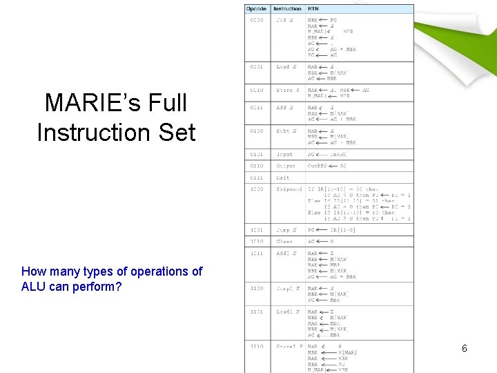
MARIE’s Full Instruction Set How many types of operations of ALU can perform? 6
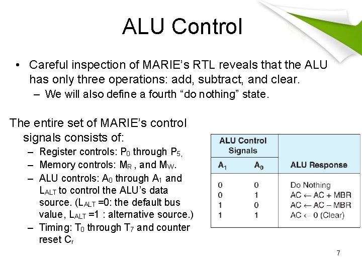
ALU Control • Careful inspection of MARIE’s RTL reveals that the ALU has only three operations: add, subtract, and clear. – We will also define a fourth “do nothing” state. The entire set of MARIE’s control signals consists of: – Register controls: P 0 through P 5, – Memory controls: MR , and MW. – ALU controls: A 0 through A 1 and LALT to control the ALU’s data source. (LALT =0: the default bus value, LALT =1 : alternative source. ) – Timing: T 0 through T 7 and counter reset Cr 7
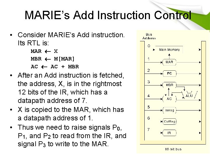
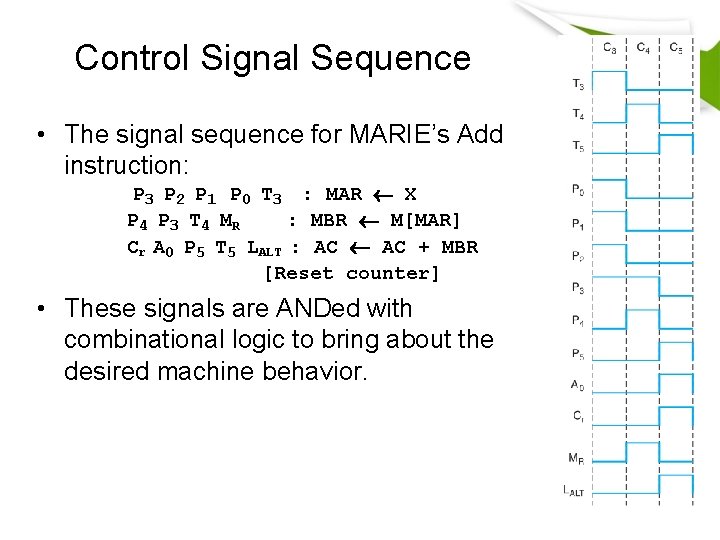
MARIE’s Add Instruction Control • Consider MARIE’s Add instruction. Its RTL is: MAR X MBR M[MAR] AC + MBR • After an Add instruction is fetched, the address, X, is in the rightmost 12 bits of the IR, which has a datapath address of 7. • X is copied to the MAR, which has a datapath address of 1. • Thus we need to raise signals P 0, P 1, and P 2 to read from the IR, and signal P 3 to write to the MAR. 8
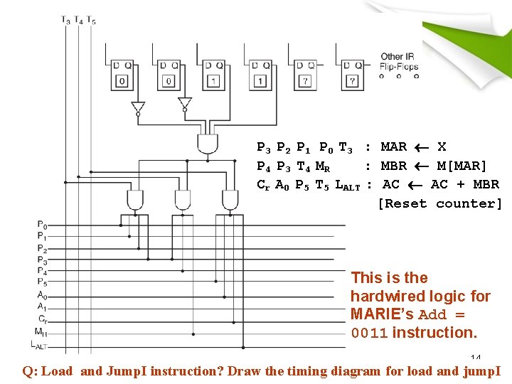
Control Signal Sequence • The signal sequence for MARIE’s Add instruction: P 3 P 2 P 1 P 0 T 3 : MAR X P 4 P 3 T 4 MR : MBR M[MAR] Cr A 0 P 5 T 5 LALT : AC + MBR [Reset counter] • These signals are ANDed with combinational logic to bring about the desired machine behavior. 9
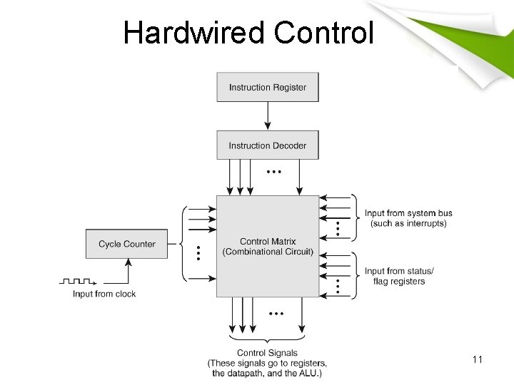
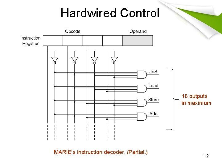
Control Unit Implementation • Two general ways control unit implementation, hardwired control and microprogrammed control. • Hardwired control: – The bit pattern of machine instruction in the IR is decoded by combinational logic. – The decoder output works with the control signals of the current system state to produce a new set of control signals. • Microprogrammed control: – Employs software consisting of microinstructions that carry out an instruction’s microoperations. • Note that the signal pattern just described is the same whether our machine used hardwired or microprogrammed control. 10
Hardwired Control 11
Hardwired Control 16 outputs in maximum MARIE's instruction decoder. (Partial. ) 12
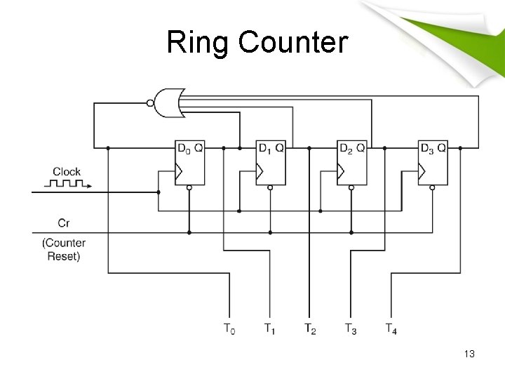
Ring Counter 13
P 3 P 2 P 1 P 0 T 3 : MAR X P 4 P 3 T 4 MR : MBR M[MAR] Cr A 0 P 5 T 5 LALT : AC + MBR [Reset counter] This is the hardwired logic for MARIE’s Add = 0011 instruction. 14 Q: Load and Jump. I instruction? Draw the timing diagram for load and jump. I
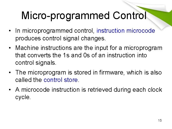
Micro-programmed Control • In microprogrammed control, instruction microcode produces control signal changes. • Machine instructions are the input for a microprogram that converts the 1 s and 0 s of an instruction into control signals. • The microprogram is stored in firmware, which is also called the control store. • A microcode instruction is retrieved during each clock cycle. 15
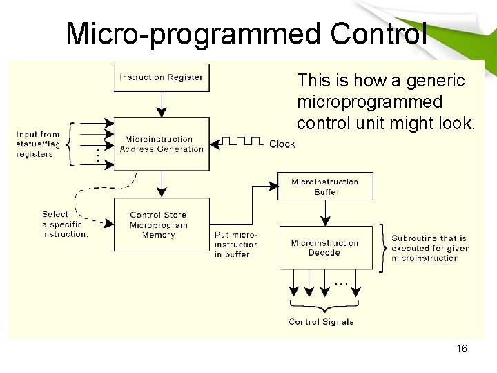
Micro-programmed Control This is how a generic microprogrammed control unit might look. 16
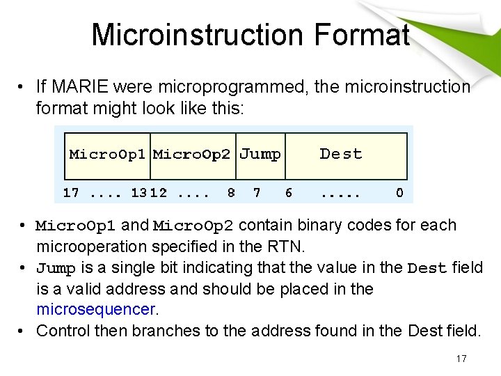
Microinstruction Format • If MARIE were microprogrammed, the microinstruction format might look like this: • Micro. Op 1 and Micro. Op 2 contain binary codes for each microoperation specified in the RTN. • Jump is a single bit indicating that the value in the Dest field is a valid address and should be placed in the microsequencer. • Control then branches to the address found in the Dest field. 17
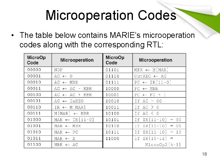
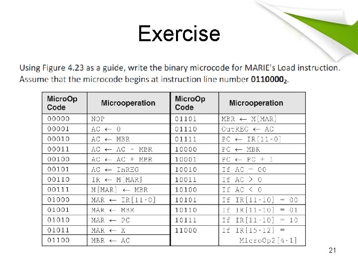
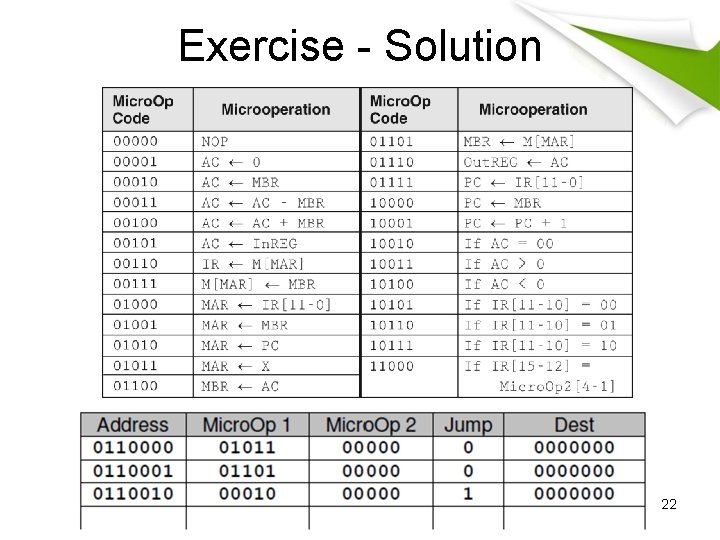
Microoperation Codes • The table below contains MARIE’s microoperation codes along with the corresponding RTL: 18
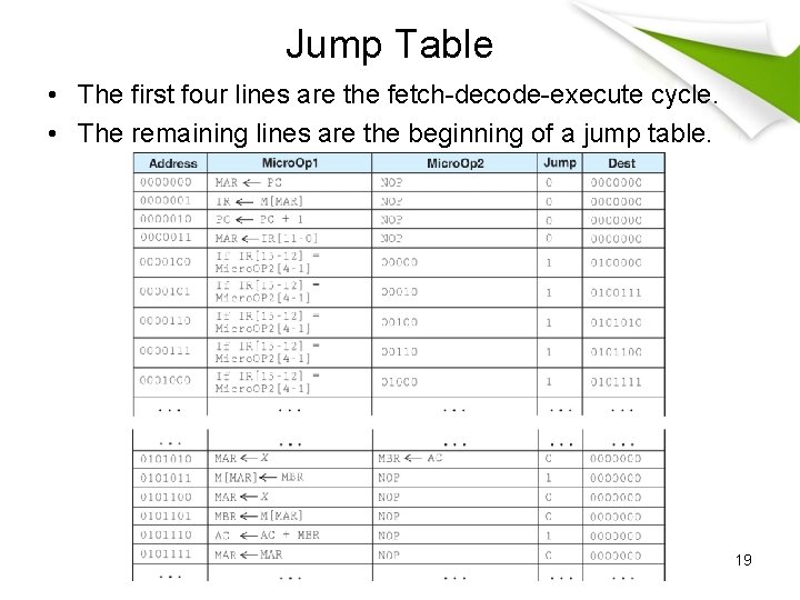
Jump Table • The first four lines are the fetch-decode-execute cycle. • The remaining lines are the beginning of a jump table. 19
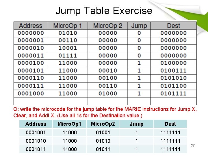
Jump Table Exercise Q: write the microcode for the jump table for the MARIE instructions for Jump X, Clear, and Add. I X. (Use all 1 s for the Destination value. ) Address Micro. Op 1 Micro. Op 2 Jump Dest 0001001 11000 01001 1 1111111 0001010 11000 01010 1 1111111 0001011 11000 01011 1 1111111 20
Exercise 21
Exercise - Solution 22
Hardware vs. Micro-programmed Control • Microinstructions are fetched, decoded, and executed in the same manner as regular instructions. • This extra level of instruction interpretation is what makes microprogrammed control slower than hardwired control. • The advantages of microprogrammed control are that it can support very complicated instructions and only the microprogram needs to be changed if the instruction set changes (or an error is found). 23