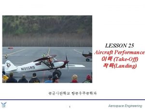
LANDING PERFORMANCE LANDING CONSIDERATIONS Factors to Consider Aircraft


- Slides: 17

LANDING PERFORMANCE

LANDING CONSIDERATIONS Factors to Consider: Aircraft Gross Weight Available Engine Thrust Field Elevation Pressure Altitude Temperature Winds Runway Length Runway Slope Runway Condition Terrain & Obstacles MEL/CDLs Icing

LANDING The Maximum Landing Weight (MLW) is computed by finding the most restrictive (lowest weight) of the following: 1. Landing Runway Limit Weight (Performance) 2. Landing Climb Limit Weight (Performance) 3. Structural Landing Limit Weight (Structural)

LANDING The regulations require specific operational limitations for stopping on the landing runway, or initial climb away from the runway during a missed approach. Weight planning and establishing weight limitations for the aircraft allows the airline to ensure the aircraft meet these requirements depending on ambient conditions. Separate weight limitations are created for the Runway (the Landing Runway Limit Weight) to cover touchdown and stopping, and for the Climb (the Landing Climb Limit Weight), which covers a missed approach or “go-around” situation. This data is found in the Runway Analysis Manual.

LANDING RUNWAY LIMIT WEIGHT The Landing Runway Weight must be such that a full stop landing can be made at the destination or alternate airport within 60% of the effective length of the runway from a point 50 feet above the runway threshold at a speed no less than 1. 3 Vso. Low visibility and wet runways each require an additional 15% margin above the 60% of the effective distance of the runway. The runway length required for landing is based on a full spoiler extension, anti-skid brakes, and flaps fully down throughout the landing roll. Reverse thrust is not considered. It results in only about 300 ft less runway in dry conditions.

LANDING SPEEDS VS (Stall Speed) Vs – stalling speed or the minimum steady flight speed at which the airplane is controllable. VSO (Stall Speed-Landing Configuration) Vso – stalling speed or the minimum steady flight speed in the landing configuration. VREF (Reference Speed) Vref – reference speed, it is normally 1. 3 x Vso. Three ways of slowing/stopping Reverse thrust, Aerodynamic braking, wheel brakes

RUNWAY CONDITIONS Dynamic Hydroplaning Occurs when a tire rolls through standing water, forms a bow wave then rolls up on top of the wave losing contact with rwy. Rule of Thumb: 9 x square root of tire pressure Viscous Hydroplaning Occurs when there is a thin film o water covering a smooth surface such as paint or rubber-coated portion of runway. Occurs much lower speed than Dynamic Hydroplaning. Reverted Rubber Hydroplaning Occurs during a locked wheel skid. Water trapped between tire and rwy is heated by friction, tire rides on pocket of steam.

LANDING RUNWAY LIMIT WEIGHT

LANDING CLIMB WEIGHT(S) The Landing Climb Limit Weight ensures compliance with both the Approach Climb and Landing Climb requirements. Approach Climb Performance (go-around or balked landing). The approach climb gradient is based on an engine inoperative, the aircraft at maximum certified landing weight, landing gear retracted, approach flaps set, and takeoff thrust on the remaining engine(s). The demonstrated climb gradient must be at least 2. 1%. Landing Climb Performance (go-around or balked landing). The landing climb gradient is based on all engines operating at takeoff thrust, full landing flaps deployed, landing gear extended, and the aircraft at maximum certificated landing weight. The gradient must be at least 3. 2%.

LANDING CLIMB WEIGHT(S)

LANDING DATA CONSIDERATIONS Landing (Runway) The 60% requirement is pre-dispatch ONLY and in the case of an in-flight emergency, the full length of the runway can be considered for stopping, using the judgment of the captain and dispatcher considering the current conditions at that airport. Go-Around (Climb) The length of the runway has no effect on the missed approach limitations of the aircraft as this is an in-flight consideration only. The requirement is for positive climb only; terrain clearance is not considered.

AIRPORT/RUNWAY ANALYSIS Prepared by independent companies (Jeppesen, Aero. Data, etc. ) or the airline Engineering Department to provide suitable performance data for takeoff and landing. Combines Airplane Flight Manual (AFM) performance during certification with extensive and thorough runway and obstacle data. Considers TERPS (Terminal Procedures) such as SIDs, Departure Procedures (DPs) and Obstacle Departure Procedures (ODPs). Airlines can create specific, ad-hoc procedures to avoid obstacles and maintain FAA performance requirements.

AIRPORT/RUNWAY ANALYSIS turns. Looks at terrain up to 30 miles or farther from the departure airport. Considers loss of climb performance in Ensures the aircraft will not exceed brake energy limits, tire speed limits, etc. Aids in maximizing payload uplift. Can account for runway construction or other shortened distances. Usually exceeds 14 CFR Part 121 and AC 120 -91 requirements to enhance safety.

AIRPORT/RUNWAY ANALYSIS Landing ASO ASI ASO WET ASI WET Anti-Skid Operative - Dry Runway Inoperative - Dry Runway Operative - Wet Runway Inoperative - Wet Runway The Ops Manual and Ops Specs for some airlines with smaller jets allow the operator to consider a wet runway to be dry for performance planning if the runway is grooved (Comair). Larger jet transports, for the most part, do not utilize this, for safety reasons.

ENGINE-OUT PROCEDURES VMC (Minimum Control Speed) Vmc – minimum control speed with the critical engine inoperative. Vmc will vary with aircraft’s CG, Vmc will be higher with the CG at its most rearward-allowed position. VXSE (Angle of Climb Speed) Vxse – best single engime angle-of-climb speed. VYSE (Rate of Climb Speed) Vyse – best single engine rate-of-climb speed.

ENGINE-OUT PROCEDURES VXSE Best angle of climb speed The greatest gain in altitude over a given horizontal distance. VYSE Best rate of climb speed The greatest gain in altitude over a given amount of time.

ENGINE OUT FERRY FLIGHTS A three or four engine turbine powered airplane may be ferried to a maintenance base with one engine inoperative if the following requirements are met: 1. Airplane model must have been test flown to show ops safe 2. Approve flight manual must contain performance data 3. Operating weight limited to minimum required for flight 4. Takeoffs are usually limited to dry runways 5. Computed T/O performance must be within acceptable limits 6. Initial climb cannot be over thickly-populated areas 7. Only required flight crewmembers may be on aircraft 8. WX conditions at T/O and Dest airports must be VFR
 Azure landing zone considerations
 Landing zone azure
 Landing gear safety devices
 Aircraft landing gear system
 Vertical game
 Kitchen labour saving devices
 Consider all factors
 Disadvantages of rsa retail savings bonds
 Explain factors to consider when proposing dishes for menus
 Factors to consider in multinational capital budgeting
 Huff's law of shopper attraction
 The apt requires a benchmark portfolio
 Edward de bono pmi
 Menu engineering worksheet
 Captive-product pricing
 What factors did you consider in acquiring territories?
 Factors to consider before going global
 General consideration of machine design
