Introduction to Unified Modeling Language UML The Unified


- Slides: 27

Introduction to Unified Modeling Language (UML)

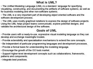
The Unified Modeling Language (UML) UML or Unified Modeling Language comes from Rumbaugh, Booch, and Jacobson (the three amigos) who combined efforts to standardize on one modeling language This is primarily a graphical communication mechanism for developers and customers We will learn some, but not all, of the UML it is very complex, few understand all of it 6 -2 2

UML The main purpose of UML is to support communication about the analysis and design of the system being developed support the movement from the problem domain in the "world" to the solution domain in the machine Two views of the same system • one view has diagrams • source code is another view Sometimes it's nice to look at the overview • Reverse engineer your code with a UML tool to see how your code looks in UML 6 -3 3

UML is a Modeling Language UML graphical notation to describe software design has rules on how to draw models of classes associations between classes message sends between objects has become the de facto industry standard Not official, but everyone uses it like a blueprint to show what is going on during analysis, design and implementation Some Projects require UML documentation 6 -4 4

UML Defined by the Authors The Unified Modeling Language User Guide, Booch, Rumbaugh, Jacobson states: The UML is a language for visualizing specifying constructing documenting the artifacts of a software intensive system 6 -5 5

First up: Class Diagrams A class diagram expresses class definitions to be implemented lists name, attributes, and methods for each class shows relationships between classes UML allows different levels of detail on both the attributes and the methods of one class could be just the class name in a rectangle or like the general form shown on the next slide 6 -6 6

Software Specification (Class Name) attribute : type = initial value class. Attribute derived. Attribute. . . method 1() method 2(parameter : Type) : return type abstract. Method() +public. Method() -private. Method() #protected. Method() class. Method(). . . 6 -7 7

Account. Collection - all. Accounts : Hash. Map +Account. Collection () +get. Account. With. ID (ID: String) : Account +add(account. To. Add: Account) : boolean +iterator() : Iterator Note: iterator is needed by the bank manager 6 -8 8

Sterotypes Stereotype is a UML element that allows designers to extend the UML vocabulary Often used to distinguish an abstract class name from an interface, both of which are written in italic <<interface>> Iterator +has. Next(): boolean +next(): Object +remove(): void 6 -9 9

Different levels of detail Tips for modeling Express as much or as little detail as needed Often, a rectangle with a name is enough perhaps a method or an attribute clarifies Simple is good Sketches on paper or white board are effective 6 -10 10

Relationships Three Relationships in UML 1) Dependency 2) Association 3) Generalization 6 -11 11

1) Dependency: A Uses Relationship Dependencies occurs when one object depends on another if you change one object's interface, you need to change the dependent object arrows point from dependent to needed objects Jukebox Card. Reader CDCollection Song. Selector 6 -12 12

2)Association: Structural Relationship Association a relationship between classes indicates some meaningful or interesting connection Associations can be labeled get. Account. With. ID for example BTW: The box with association is an official UML comment, must have that fold association Jukebox get. Account. With. ID 1 1 Jukebox. Account. Collection 6 -13 13

Associations imply our knowledge that a relationship must be preserved for some time (0. 01 ms to forever) Between what objects do we need to remember a relationship? • Does a Transaction need to remember Account? • Would Account. Collection need to remember Accounts? Account. Collection Stores 1 0. . * Account 6 -14 14

Notation and Multiplicity Adornments UML Association: a line between two concepts and a name zero or more; they are bi-directional T * "many" can have a multiplicity 1. . * T one or more exist in class diagrams 1. . 52 Multiplicity adornments 5 T one to fifty two T exactly five 6 -15 15

Association Names • Read these Type-Verb. Phrase-Type • POST is a Point of Sale Terminal) • Not shown here: Attributes and Methods • This just shows associations between objects 6 -16 16

Aggregation: A Special Association Aggregation: whole/part relationships An association that models HAS-A relationships The objects can exist independently of each other No one object is more important than the other Place an open diamond on the whole School contains a collection of Student objects School 1. . * * Student In Java, this is the same as an association, an instance variable, no special syntax 6 -17 17

Composition: A Special Association Composition: Stronger relationship One can not exist without the other If the school folds, students live on but the departments go away with the school If a department closes, the school can go on AIC* e. g. School 1. . * 1 1. . * Department * Student Model aggregation or composition? When in doubt, use association (just a simple line) don't sweat the diff in 335 6 -18 18

Active Learning In teams of two or three, using examples in these slides and the names of the objects we discovered in the Five Card Draw, complete a class diagram that shows a design of a software system to model the game as it would exist on a gambling website. 6 -19 19

Draw rectangles for classes Include the class name In at least five classes, write one Draw associations between objects missing diamonds and arrows are okay one solid line will suffice an association implies there will be some relationship between the objects as some point There is a separate handout for this You must be in class to get credit 6 -20 20

Sequence Diagrams Interaction diagrams describe how groups of objects collaborate in some behavior The UML defines several forms of interaction diagram, the most common is the sequence diagram A class diagram shows a fixed view of a system A sequence diagram represents a dynamic view of a system by capturing message sends over time Can document a scenario such as Dealer deals cards to all players Withdraw Money when there is enough balance Withdraw Money when there is not enough balance 6 -21 21

6 -22 22

Sequence Diagrams Not good at showing details of algorithms such as loops and conditional Good at showing the calls between participants Gives a good picture about which participants are doing which processing 6 -23 23

More Distributed Control Shown here 6 -24 24

Syntax Objects are lined up on top in rectangles Object names : Card. Reader Dashed lines represent lifetime of objects Rectangles are activation lines When the object is "alive" Activation bar of the receivers of the message is smaller than the sender's activation bar Not much detail written 6 -25 25

Another Example http: //www. ifi. uio. no/in 219/verktoy/doc/html/doc/user/mg/dgmsuml 6. html Scenario: The user tries to use an ATM, but the account is not known 6 -26 26

http: //www. visual-paradigm. com/ VPGallery/diagrams/Sequence. html Scenario: The user successfully withdraws money from an ATM 6 -27 27
 Uml 物件圖
 Introduction to the unified modeling language
 Introduction to unified modeling language
 Mercer oneview login
 Unified modeling language tutorial
 Unified modeling language ppt
 Pengertian unified modeling language
 What is uml
 Uml diagram nasıl çizilir
 Sebutkan fungsi dari
 Object diagram captures the behavior of a single use case.
 Mof uml
 Modeling role modeling theory
 Relational modeling vs dimensional modeling
 Superstruture
 Common mechanisms in basic structural modeling
 Uml modeling tutorial
 Uml 0..*
 Uml 1..*
 Introduction to modeling and simulation
 Pengertian pemodelan dan simulasi
 What is vrml
 Omg systems modeling language
 What does vrml stand for
 Universal modelling language
 Uniform modeling language
 Language modeling incorporates rules of
 Java modeling language
