INTERNAL COMBUSTION I C ENGINES INTERNAL COMBUSTION I
 ENGINES")
INTERNAL COMBUSTION (I. C. ) ENGINES
 ENGINES Heat Engine Ø A heat engine is a")
INTERNAL COMBUSTION (I. C. ) ENGINES Heat Engine Ø A heat engine is a device which converts the chemical energy of fuel into heat energy, and this heat energy is converted into mechanical energy. Types of Heat Engines Ø External Combustion Engine Ø Internal Combustion Engine External Combustion Engine Ø The combustion takes place in a specially designed area called furnace. Ø The products of combustion are expanded in gas turbine to develop mechanical power. Ø The heat developed can also be used to raise pressure and temperature of another working fluid to develop mechanical power. Ø Because of its size not suitable for mobile plants.
 ENGINES Internal Combustion Engine Ø The combustion takes place")
INTERNAL COMBUSTION (I. C. ) ENGINES Internal Combustion Engine Ø The combustion takes place inside the cylinder itself with air inducted from outside. Ø The chemical energy of fuel raises pressure and temperature of the products of combustion. Ø The hot gases are then expanded to develop mechanical power and some heat is rejected to the atmosphere. Ø Suitable for transport system in automobiles, diesel locomotives, aero planes,
 ENGINES Classification Depending on the type of fuel used")
INTERNAL COMBUSTION (I. C. ) ENGINES Classification Depending on the type of fuel used Ø Petrol Engine Ø Diesel Engine Ø Gas Engine Depending on the type of mechanical cycle Ø 2 – stroke Ø 4 – stroke Depending on the type of thermodynamic cycle Ø Otto cycle Ø Diesel cycle Ø Dual cycle Depending on the ignition system used Ø Spark ignition Ø Compression ignition

Depending on the cooling system employed Ø Air cooled Ø Water cooled Depending on the number of cylinders used Ø Single cylinder Ø Multi cylinder Depending on the axis position Ø Horizontal Ø Vertical or radial Depending on the type of inlet condition Ø Naturally aspirated Ø Supercharged Depending on the use or application Ø Automobile Ø Marine Ø Locomotive Ø Stationary

I. C. ENGINES & ITS COMPONENTS

I. C. ENGINES & ITS COMPONENTS Major components Ø Ø Ø Cylinder. Piston Head Connecting rod Crankshaft Crank Inlet Exhaust Valves Flywheel Carburettor/Fuel Pump Cam Shaft Cam follower Pushrods & Rocker arm

4 – STROKE I. C. ENGINES The four-stroke cycle 1=TDC 2=BDC A: Intake B: Compression C: Power D: Exhaust
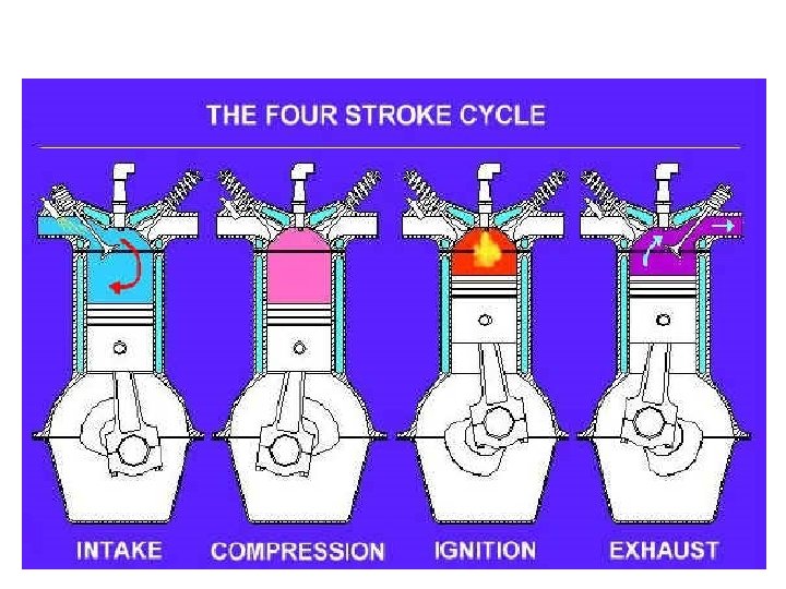

4 – STROKE ENGINES Working of 4 – Stroke Engine Stroke Suction Petrol Engine The piston moves from TDC to BDC and sucks in air-fuel mixture supplied by carburettor Diesel Engine The piston moves from TDC to BDC and sucks in only air Compres The piston moves from BDC to TDC and compresses the charge of air-fuel sion The piston moves from BDC to TDC and compresses the air increasing its pressure and temperature Ignition Timing Spark occurs 40º before TDC The fuel valve opens 12º before TDC and remains open for 16º after TDC Power Due to high pressure & temperature the piston is pushed towards BDC and gas expands doing work on piston Exhaust The flue gases which are expanded are exhausted through the exhaust valve as the piston moves towards TDC mix. increasing its temp & pressure

TWO STROKE ENGINE - WORKING

TWO STROKE ENGINE - WORKING

COMPARISON OF 2 & 4 – STROKE ENGINES 2–Stroke Engine 4–Stroke Engine Cycle is completed in two strokes of piston or one revolution of crankshaft. Cycle is completed in four strokes of piston or two revolution of crankshaft. Ports available are inlet, exhaust and transfer. Inlet and exhaust valves are used. Piston crown has special shape to act as deflector. No special piston shape. Higher fuel consumption due to loss of charge. No charge is lost and are hence efficient. Causes pollution due to loss of charge. Less pollution as charge is completely burned. Theoretically, produces double power for the same speed when compared to 4 stroke
- Slides: 13