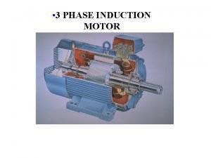
Induction Machines THREEPHASE INDUCTION MOTORS Principle Of Operation


- Slides: 15

Induction Machines THREE-PHASE INDUCTION MOTORS Principle Of Operation

• Rotating Magnetic Field: When the stator winding of a three-phase induction motor is connected to a three-phase power source, it produces a magnetic field Bs that revolves around the rotor at: 1. Constant speed, which is called the synchronous speed, Ns, and 2. Constant in magnitude. – AC Machine with Two-Pole: • These magnetic poles complete one mechanical rotation around the stator surface for each electrical cycle of the applied current. • The relationship between the electrical angle e and the mechanical angle m in this stator is e = m 2 2 -Pole 3 induction motor

– AC Machine with Two-Pole: • Thus, the electrical frequency of the current is equal to the mechanical frequency of rotation: fe = fm and e = m • Where fm and m are the mechanical speed in revolutions per second and radians per second, while fe and e are the electrical speed in hertz and radians per second. – AC Machine with Four-Pole: • The relationship between the electrical angle e and the mechanical angle m in this stator is e = 2 m • Thus for the four-pole winding, the electrical frequency of the current is twice the mechanical frequency of rotation: fe = 2 fm and e = 2 m 4 -Pole 3 induction motor 17

2 -Pole – AC Machine with P-Pole: • In general, if the number of magnetic poles on an AC machine stator is P, then the electrical and mechanical quantities on the stator are related by 4 -Pole 6 -Pole e = m N S N e = 2 m N S S e = (P/2) m e = 3 m N fe = (P/2) fm N N S S S e = (P/2) m 0 90 180 270 The mechanical angle m 4 360

– If Ns is the mechanical speed in revolution per minute (rpm), then fm N s rev min 60 sec Ns 60 [rev / s] – The electrical frequency (fe) in Hertz can be related to the resulting mechanical speed (Ns) of the magnetic fields in revolutions per minute. This relationship is P N PN P s fe f m �s 2 2 60 120 Then N or s s 2 60 1 2 0 fe in revolutions per minute (rpm), P Ns 2 120 f 60 P e 2 f e P/2 s 5 e P/2 [rad/s]

– The revolving field B induces electromotive force (emf) in the rotor winding. The voltage eind induced in the rotor is given by: eind = (v x B) L ; where v is the relative velocity – Since the rotor winding forms a closed loop, the induced emf in each coil gives rise to an induced current i in that coil, . – When a current-carrying coil i is immersed in a magnetic field B, it experiences a force F (or torque T) that tends to rotate it. F = i (L x B) – The torque thus developed is called the starting torque. – If the load torque TL is less than the starting torque Tst, the rotor starts rotating. TL < Tst – The force developed and thereby the rotation of the rotor m is in the same direction as the revolving field B. B m Tst 6

• No-load Case: – Under no-load, the rotor soon achieves a speed nearly equal to the synchronous speed Ns. – However, the rotor can never rotate at the synchronous speed because the rotor coils would appear stationary with respect to the revolving field and there would be no induced emf (eind = 0) in them. – In the absence of an induced emf (eind = 0) in the rotor coils, there would be no current in the rotor conductors (i = 0) and consequently no force (F = 0) would be experienced by them. – In the absence of a force (F = 0), the rotor would tend to slow down. – As soon as the rotor slows down, the induction process takes over again. 7

1. If the induction motor’s rotor were turning at synchronous speed 2. Rotor bars would be stationary relative to the magnetic field 3. No induced voltage 4. No rotor current 5. No rotor magnetic field 6. Induced torque Tind = 0 7. Rotor will slow down due to friction eind = 0 The operation of three-phase induction motor under no load 8

• Conclusion: – The rotor receives its power by induction only when there is a relative motion between the rotor speed Nm and the revolving field Ns. – An induction motor can thus speed up to near synchronous speed but it can never reach synchronous speed, Ns. Therefore, there is a finite upper limit to the motor’s Nm < Ns speed. – Since the rotor rotates at a speed not equal to the synchronous speed Ns of the revolving field, an induction motor is also called an asynchronous motor. 9

– Let Nm (or m) be the rotor speed at a certain load. With respect to the rotor, the revolving field B is moving ahead – The relative speed Nr is. Nalso at a relative speed r of called the slip speed. This is the speed with which the rotor is slipping behind a point on a or N r revolving Ns N r torque. s m m in order to produce fictitious pole – However, it is a common practice to express slip speed in terms of the slip (s), which is a ratio of the slip speed to the synchronous speed. N r r s Ns s or N s Nm s Ns s 10

– Although the above equation yields the slip s on a per-unit basis, it is customary to express it as a percentage of synchronous speed (percent slip). – In terms of the synchronous speed Ns and the per-unit slip s, we can express the rotor speed Nm as N m (1 s)N s or m (1 s) s – When the rotor is stationary, the per-unit slip s = 1 and the rotor appears exactly like a short-circuited secondary winding of a transformer. – Thus, the rotor frequency fr of the induced emf in the rotor winding is the same as the frequency of the stator fe. fr = fe at s=1 11

– However, when the rotor rotates, it is the relative speed of the rotor Nr (or r) that is responsible for the induced emf in its windings. Thus, the frequency of the induced emf in the rotor is 120 f Nr �r P P(N s N m ) fr 120 PN fr �r 120 multiply the equation by Ns Ns PNs N m fr 120 N s fr s f The above equation highlights the fact that the rotor frequency depends upon the slip (speed) of the motor. 12

0 1 f IM Operating Region – However, the rotor frequency decreases with the decrease in the slip. As the slip approaches zero, so does the rotor frequency. Nm Ns s 0 fr 0 or DC – An induction motor usually operates at low slip. Hence the frequency of the induced emf in the rotor is low. For this reason, the core loss in the rotor magnetic circuit is most often ignored. 13

EXAMPLE 1 -1 A 208 -V, 60 -Hz, 4 -pole, three-phase induction motor has a full-load speed of 1755 rpm. Calculate (a) its synchronous speed, (b) the slip, and (c) the rotor frequency. SOLUTION (a) The synchronous speed of the induction motor is 120 f 120 60 1800 rpm P 4 (b) At full load, the slip is N N m 1800 1755 0. 025 s s Ns 1800 Ns or 2. 5% (c) The rotor frequency at full load is fr s fe 0. 025 60 1. 5 Hz 14

• Principle of Operation: 1. The rotor speed of a 440 -V, 50 -Hz, 8 -pole, three-phase induction motor is 720 rpm. Determine (a) the synchronous speed, (b) the slip, and (c) the rotor frequency. 2. If the rotor frequency of a 6 -pole, 50 -Hz, three-phase induction motor is 3 Hz, determine (a) the slip and (b) the rotor speed. 3. The magnetic field produced by a three-phase induction motor revolves at a speed of 900 rpm. If the frequency of the applied voltage is 60 Hz, determine the number of poles in the motor. When the rotor turns at a speed of 800 rpm, what is the percent slip of the motor? 4. The frequency of the induced emf in the secondary winding of an 8 -pole, three-phase induction motor is 10 Hz. At what speed does the magnetomotive force (mmf) of the secondary revolve with respect to the secondary winding? 5. A 2 -pole, 230 -V, 50 -Hz, three-phase induction motor operates at a speed of 2800 rpm. Determine (a) the per-unit slip and (b) the frequency of the induced emf in the rotor. 6. A 12 -pole, 440 -V, 400 -Hz, three-phase induction motor is designed to operate at a slip of 5% on full load. Determine (a) the rated speed, (b) the rotor frequency, and (c) the speed of the rotor revolving field relative to the rotor. 15
 Induction motors procurement
 4 quadrant operation of induction motor
 4 quadrant operation of induction motor
 Inductie matematica
 Geometric sequence closed form
 Principle of vector control of induction motor
 Principle of mathematical induction
 Synchronous machine
 What is hunting in synchronous motor
 Narayan motors
 How are electromagnets used in doorbells
 Scott dc motors
 Tesla motors toronto
 Module 00105 introduction to construction drawings answers
 Lisa gue
 Axinte motors
