Inductance We know already changing magnetic flux creates


- Slides: 11

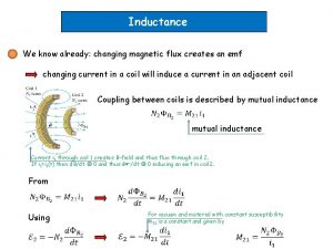
Inductance We know already: changing magnetic flux creates an emf changing current in a coil will induce a current in an adjacent coil Coupling between coils is described by mutual inductance Current i 1 through coil 1 creates B-field and thus flux through coil 2. If i 1=i 1(t) then d. B/dt 0 and thus d /dt 0 inducing an emf in coil 2. From For vacuum and material with constant susceptibility M 21 is a constant and given by Using

with For the vacuum case (but also in general) mutual inductance depends only on coil geometry with Mutual inductance is measured in Henry where 1 H=1 Wb/A=1 Vs/A=1Ωs=1 J/A 2 - Mutual inductance can give rise to cross-talk in electronic circuits - Mutual inductance has important applications, e. g. , in transformers

Many applications happen in AC circuits (see textbook). Here a collection: Transformers Metal detectors Here we have a brief look at the Tesla coil Current i 1 through coil 1 creates B-field and flux solenoid 1 is long compared to solenoid 2 M depends only on geometry and in particular on product N 1 N 2.

To see how a Tesla coil can create a vary large emf let’s have a look to an example Drive a current i 2(t)through solenoid 2 (blue) by Flux through solenoid 1 is given emf induced in solenoid 1 reads: see slide 11 for derivation of resonance frequency in LC-circuit Hallmark of Tesla coil is the loose/critical coupling (large air gap) between the solenoids 1 and 2 to prevent damage (insulation between tightly coupled solenoids would experience dielectric breakdown). From http: //tesladownunder. com/Tesla_coils_intro. htm Note, I did not check the scientific validity of the information provided on this web-site

Self-Inductance and Inductors The concept that a changing flux induces an emf can also be applied in the case of a single solenoid Self-inductance With A device designed to have a particular inductance L is called an inductor Circuit symbol Examples from http: //upload. wikimedia. org/wikipedia/commons/2/27/Aplikimi_i_feriteve. png

The effect of an inductor in a circuit Let’s compare resistor and inductor Current flowing through resistor R gives rise to potential drop Emf opposes current change Potential drop Note: Sign opposite to emf Example: Inductance of an air core toroidal solenoid 1) Determine B from Ampere’s law r 2) Determine flux through one loop 3) Determine emf of solenoid and compare with

Magnetic field Energy We will see that similar to the electric field there is energy stored in a magnetic field Energy stored in an Inductor Let’s calculate the energy input U needed to establish a current I in an ideal (zero resistance) inductor with inductance L With we obtain for the power, P, delivered to the inductor For the energy delivered after time, t, we obtain Changing integration variable from t to i we obtain Energy stored in an inductor when permanent current I is flowing

We now want to use to see that the energy is stored in the field (very much in analogy to the transition from energy in a capacitor to energy stored in the electric field ) Let’s recall the inductance L of a toroidal inductor Volume, V, which is filled with a magnetic field of magnitude where A is the area of the cross-section The energy can be expressed as for i=I which yields the energy density u=U/V for vacuum or in a magnetic material

R-L circuits Kirchhoff’s loop rule t=0 is time when switch is closed all the voltage drops across L and thus i(t=0)=0 Solving the differential equation:

i t What happens if we release energy stored in the solenoid Kirchhoff’s loop rule: i I 0/e t

L-C circuits L-C circuit shows qualitative new behavior Because there is no power dissipation, energy once stored in C or L will periodically redistribute between energy in E-field and B-field From http: //en. wikipedia. org/wiki/LC_circuit Kirchhoff’s loop rule Compare with harmonic oscillator
 Remanent magnetization
 Difference between magnetic flux and magnetic flux density
 How to find magnetic flux
 Already can or can already
 On an atomic level what creates a magnetic field
 You should already know
 Pronunciation poem i take it you already know
 Lets see what you already know
 What do you already know about rainforests?
 How much do you already know about
 What do we already know
 Structure of skeletal muscle
