Ground Improvement Project Large water storage tanks Carrington


; • Controlled Modulus Columns")
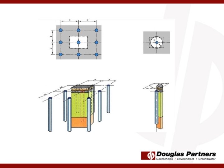
 A “unit cell” axisymmetric model consisting of the CSC and its surrounding soils")
 with equivalent composite CSC/Soil Zone")


")
 Typical Column Load Test Result 400 350 300 250 200")

- Slides: 29
Ground Improvement Project – Large water storage tanks Carrington NSW Douglas Partners’ Technical Seminar 2019 Scott Mc. Farlane & Richard Merifield
Background • Douglas Partners are a trusted consultant to PWCS; • PWCS needed to upgrade their stormwater management system; • PWCS engaged GHD as the design consultant (civil, hydraulic, mechanical, electrical & geotechnical); • PWCS provided GHD previous nearby geotechnical data (by DP) to assist GHD with conceptual geotechnical ground improvement options for tank; • PWCS provided DP the concept geotechnical design options by GHD to develop scope of works (i. e. data report).
Stormwater Management System • Manage stormwater to minimise off-site uncontrolled discharge; • Above ground steel tanks; • Supported on concrete slab; • Tank 1 – 20 m dia, 11 m high, 5 Ml; • Tank 2 – 32 m dia, 11 m high, 8 Ml; • Tank 3 – 32 m dia, 11 m high, 8 Ml; • Pipeline to connect into existing pond. Trench to be excavated adjacent to rail line.
Previous Data Fill Soft Clay VL Sand -0 Clay / Silt and Sand -10 Dense Sand Stiff Clay -20 Very Stiff to Hard Clay -30 -40 Rock
GHD Concept Ground Improvement Options Ground Improvement Option Do nothing Design Details - Estimated Post Construction Settlement (mm) 700 Constraints Settlement Preload CFA piles Driven Piles Cutter Soil Mixing (CSM) 8 m high preload (3 month wait) 600 mm dia; Installed to >35 m, 3 m c/c 400 mm sq; Installed to >35 m, 2. 5 m c/c CSM to 35 m 15% area replacement ratio 5 to 10 With preload: 20 mm Without: 100 mm Depth of piles, ASS Depth of Piles 250 to 300 Space, time PWCS – very risk adverse with any ground improvement (past experience)
DP Difference
DP Revised Scope • Investigation – Provide data to GHD to undertake Design; • Parallel modelling to compare with GHD design; • Review technical specification; • Review tenders methodology; • Review preferred tenderers design, QA and alternate design.
Investigation Geotechnical Risks • Soft clay layer? • Sand stratum? • Deeper clay? • Ground water? • Rock strength?
Subsurface Profile Tank 1 – 20 m dia Tank 2 – 32 m dia
Design & Analysis
Tank Design Loads Design Life = 50 years
Serviceability Criteria • Max settlement at centre ≤ 100 mm; • Max settlement around perimeter ≤ 100 mm; • Max settlement between centre and edge ≤ 40 mm; • Max edge to edge tilt ≤ 30 mm; • Differential settlement ≤ 1 in 500.
Conceptual Time-Settlement Behaviour
Initial Ground Improvement Options • No Ground Improvement; • Piles with Pile Transfer Layer (PTL); • Deep Soil Mixing (GHD preference); • Tank Interaction (3 D analysis). Max Total Settlement: Case 1 – 71 300 80 mm 76 mm Case 2 – 53 225 mm 60 mm
Initial Tender Review – Mix Soil Option • Large QA component in design spec by GHD: • Sampling and lab mix design to determine strength properties; • Additional CPTs; • Trial sites (curing time); • Core sampling of mixed soil; • Lab testing during mixing; • Column Penetration Test or Pull-out resistance test. • 1 m preload.
Alternative Tender – Rigid Inclusions • Concrete Injected Columns (CIC); • Controlled Modulus Columns (CMC); • Controlled Stiffness Columns (CSC).
a) A “unit cell” axisymmetric model consisting of the CSC and its surrounding soils was analysed; b) Based on the results from a), an equivalent set of soil properties was generated; c) Using the result from b), a larger model was generated. Plaxis 2 D Unit Cell Model of CSC
Plaxis 2 D axisymmetric model (half model) with equivalent composite CSC/Soil Zone
Tank Total Settlement mm Sustained Constant Load – 120 k. Pa Keller Prediction DP Prediction Tank 1 (20 m dia) 74 62 Tank 2 (32 m dia) 86 71
QA During Construction • Proof rolling & Plate Load Testing rather than density testing of working platform; • Additional CPTs; • Concrete testing (by others); • Review of concrete takes & penetration depths; • Plate load testing of installed columns (similar to pile test)
Plate Load Testing – Working Platform
Installation of Trial Columns
Installation of Trial Columns
60 50 40 30 20 10 0 5/ Stats Range Average No. Metres per day No. of Piles per Day 72 – 400 8 – 53 264 35 No of Piles per 450 400 350 300 250 200 150 100 50 0 18 /2 5/ 018 20 /2 5/ 018 22 /2 5/ 018 24 /2 5/ 018 26 /2 5/ 018 28 /2 5/ 018 30 /2 01 8 6/ 1/ 20 6/ 18 3/ 20 6/ 18 5/ 20 6/ 18 7/ 20 18 Number of Metres Production Rate of Columns
Column Load Testing (10 MPa – 7 days)
Pile Load (k. N) Typical Column Load Test Result 400 350 300 250 200 150 100 50 0 0 Column Diameter – 0. 4 m Column Depth – 7. 5 m 5 10 Deflection (mm) 15 20 Total No. of Column Tests – 9 Range of Max Deflection – 2. 1 to 28 mm
Thanks to All Involved with this Project 41. 75 310. 5 Ground Test Melbourne Lab Newcastle Geo 487. 5 Newcastle Lab 66. 25