FUNDAMENTALS WORK Work Force x Distance POWER power


 which has three major parts; the compressor,")


- Slides: 16
FUNDAMENTALS WORK Work = Force x Distance POWER power = work done ÷ time taken ENERGY 1 -POTENTIAL ENERGY (Potential Energy = Force x Distance ) 2 -KINETIC ENERGY Energy
FORCE AND MOTION
PRINCIPLES OF JET PROPULSION To every action there is an equal and opposite reaction THRUST CALCULATION Thrust = Mass x Acceleration W = the weight of the body g = the gravitational constant ACC ELERATION =V 2 – V 1 THRUST =
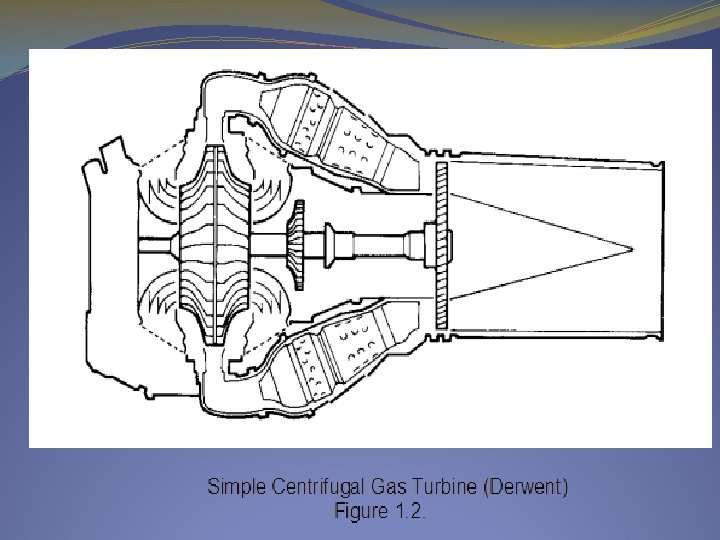
GAS TURBINES A gas turbine engine is essentially a heat engine using a mass of air as a working fluid to provide thrust. To achieve this, the mass of air passing through the engine has to be accelerated, which means that the velocity, (or kinetic energy), of the air is increased. To obtain this increase, the pressure energy is first of all increased, followed by the addition of heat energy, before final conversion back to kinetic energy in the form of a high velocity jet efflux.
simplest form of gas turbine engine (turbojet) which has three major parts; the compressor, the combustion section and the turbine. A shaft connects the compressor and the turbine to form a single, rotating unit. These engines produce thrust in the manner described in the Brayton Cycle.
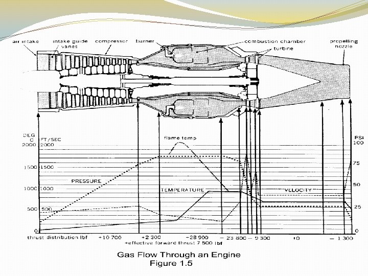
• The air entering the engine is compressed. • Heat is added to the air by burning fuel at a constant pressure, thereby considerably increasing the volume of the resulting gas. • The gases resulting from combustion expand through the turbine, which converts some of the energy in the expanding gases into mechanical energy to drive the compressor. • The remainder of the expanding gases are propelled through the turbine and jet pipe back to the atmosphere where they provide the propulsive jet. There are three main stages in the engine working cycle during which the changes discussed occur: • During compression. Work is done on the air. This increases the pressure and temperature and decreases the volume of air. • During combustion. Fuel is added to the air and then burnt. This increases the temperature and volume of the gas, whilst the pressure remains almost constant (the latter being arranged by design in a gas turbine engine). • During expansion. Energy is taken from the gas stream to drive the compressor via the turbine; this decreases the temperature and pressure, whilst the volume increases. The rapidly expanding gases are propelled through the turbine and jet pipe to give a final momentum that is much greater than the initial momentum; it is this change in momentum which produces the propulsive jet.
CHANGES IN TEMPERATURE, PRESSURE AND VELOCITY TEMPERATURE AND PRESSURE The more efficient the compressor, the higher is the pressure generated for a given work input - i. e. for a given temperature rise of the gas. Conversely, the more efficiently the turbine uses the expanding gas, the greater is the output of work for a given temperature drop in gas. VELOCITY AND PRESSURE During the passage of the air (gas) through the engine, aerodynamic and energy requirements demand changes in its velocity and pressure. For example, during compression a rise in the pressure of the air is required with no increase in its velocity. After the air has been heated and its internal energy increased by combustion, an increase in the velocity of the gases is necessary to cause the turbine to rotate. Also at the propelling nozzle, a high velocity is required, for it is the change in momentum of the air that provides the thrust on the aircraft. Local decelerations of gas flow are also required - for example, in the combustion chambers to provide a low
ENGINE CONFIGURATIONS There are two main types of gas turbine engines: • Reaction engines, which derive their thrust by jet reaction • Power engines, which provide a mechanical output to drive another device. REACTION ENGINES a)Turbojet engines b)Low and Medium By-pass or turbofan engines c)High by-pass turbofan engines POWER ENGINES a)Turboprop Engines b)Turboshaft Engines
Turbojet engines The turbojet was the first type of jet engine developed. In this engine all the air passes through the core engine (i. e. the compressor, combustor and turbine). The engine may be single shaft as in the Avon engine, or twin shafted as in the Olympus 593 fitted to Concorde. These engines are noisy and are not the most fuel efficient for normal use, however for high altitude high speed flight they are in a class of their own.
Low and Medium By-pass or turbofan engines These engines will have two or three shafts. The Low Pressure (LP) shaft drives a larger diameter compressor. Some of the air produced by-passes the core engine (hence the name) and is used to provide thrust. The core airflow provides power for the compressors and thrust. These engine are quieter than turbojets and more fuel efficient. The Spay and Toy engines fall into this category. The bypass ratio is determined by the ratio of the air in flowing through the by-pass to the air passing through the core of the engine. Low by-pass less than 2: 1, medium by-pass 2: 1 to 4: 1, high by pass greater than 5: 1.
High by-pass turbofan engines These engines have very large fans driven by a relatively small core engine. Often the fan is geared to run at a lower speed than the LP turbine, which gives the turbine mechanical advantage and also allows it to run at higher speed where it is more efficient. The ALF 502, RB 211 and the Trent engines are all high by-pass High by-pass engines are very fuel efficient, powerful and quiet. These engines have a very large diameter which does give drag problems, and are not suitable for high speed flight as the blade tips will suffer compressibility problems as they approach the speed of sound.
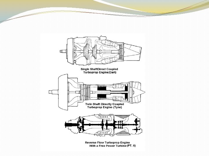
Turboprop Engines Turboprop engines extract most of the energy from the gas stream and convert it into rotational energy to drive a propeller. The engines are either single or twin shaft and may be direct drive where the LP or main shaft drive the propeller through a gearbox, or they may have a separate power turbine to drive the propeller. Turboprop engines differ from high by-pass turbofans in that the propeller does not have an intake to slow and prepare the air before passing through it. The propeller therefore has to meet the demands of airspeed etc. Examples of turboprops are the Dart, PW 125 and Tyne engines.
Turboshaft Engines These engines are used in helicopters. They share many of the attributes of turboprop engines, but are usually smaller. They do not have propeller control systems built into the engine and usually do not have many accessories attached such as generators etc. as these are driven by the main rotor gearbox. Modern turbo shaft and turbo prop engines run at constant speed which tends to prolong the life of the engine and also means that they are more efficient as the engine can run at its optimum speed all the time.