ENGIN 112 Intro to Electrical and Computer Engineering
- Slides: 17
ENGIN 112 Intro to Electrical and Computer Engineering Lecture 21 Analyzing Sequential Circuits ENGIN 112 L 21: Analyzing Sequential Circuits October 22, 2003
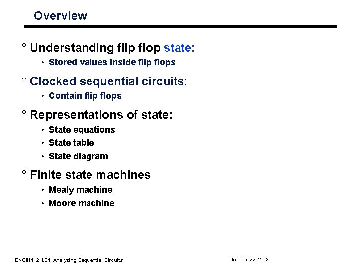
Overview ° Understanding flip flop state: • Stored values inside flip flops ° Clocked sequential circuits: • Contain flip flops ° Representations of state: • State equations • State table • State diagram ° Finite state machines • Mealy machine • Moore machine ENGIN 112 L 21: Analyzing Sequential Circuits October 22, 2003
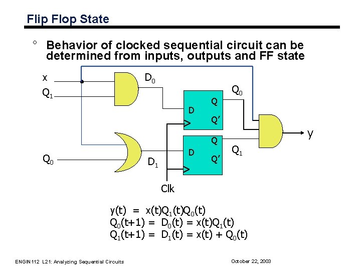
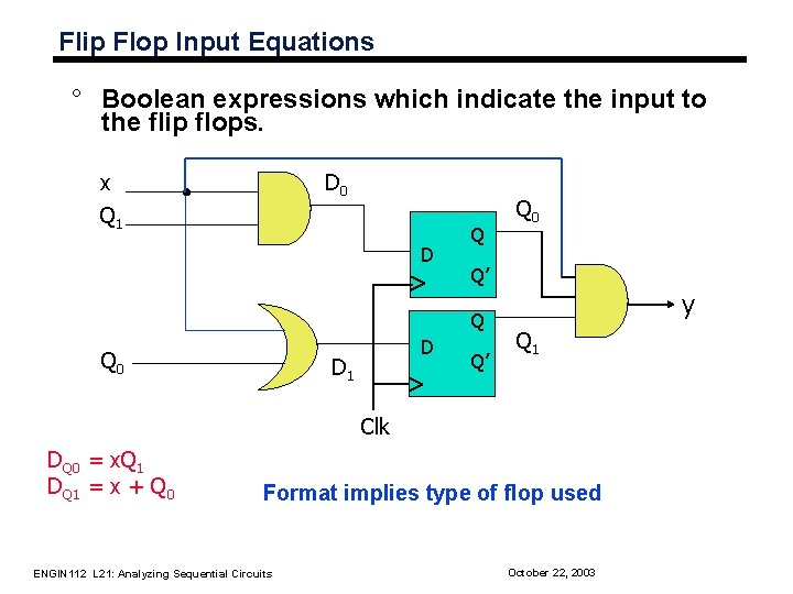
Flip Flop State ° Behavior of clocked sequential circuit can be determined from inputs, outputs and FF state x Q 1 D 0 D Q Q’ Q Q 0 D D 1 Q 0 Q’ y Q 1 Clk y(t) = x(t)Q 1(t)Q 0(t) Q 0(t+1) = D 0(t) = x(t)Q 1(t) Q 1(t+1) = D 1(t) = x(t) + Q 0(t) ENGIN 112 L 21: Analyzing Sequential Circuits October 22, 2003
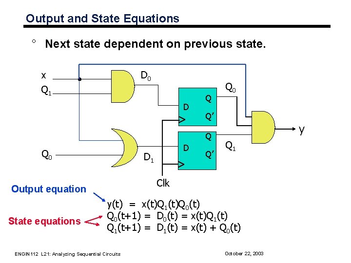
Output and State Equations ° Next state dependent on previous state. x Q 1 D 0 D Q Q’ Q Q 0 D 1 Q’ y Q 1 Clk Output equation State equations D Q 0 y(t) = x(t)Q 1(t)Q 0(t) Q 0(t+1) = D 0(t) = x(t)Q 1(t) Q 1(t+1) = D 1(t) = x(t) + Q 0(t) ENGIN 112 L 21: Analyzing Sequential Circuits October 22, 2003
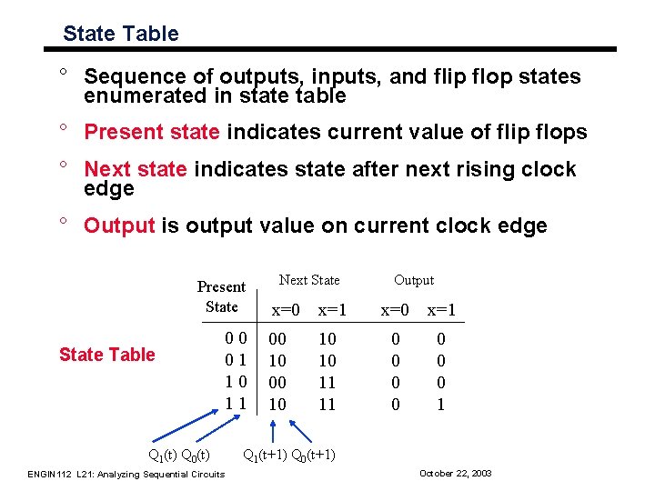
State Table ° Sequence of outputs, inputs, and flip flop states enumerated in state table ° Present state indicates current value of flip flops ° Next state indicates state after next rising clock edge ° Output is output value on current clock edge Present State Table 00 01 10 11 Q 1(t) Q 0(t) ENGIN 112 L 21: Analyzing Sequential Circuits Next State Output x=0 x=1 00 10 10 10 11 11 0 0 0 0 1 Q 1(t+1) Q 0(t+1) October 22, 2003
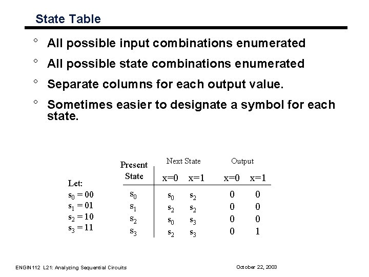
State Table ° All possible input combinations enumerated ° All possible state combinations enumerated ° Separate columns for each output value. ° Sometimes easier to designate a symbol for each state. Let: s 0 = 00 s 1 = 01 s 2 = 10 s 3 = 11 Next State Present State x=0 s 1 s 2 s 3 s 0 s 2 ENGIN 112 L 21: Analyzing Sequential Circuits x=1 s 2 s 3 Output x=0 x=1 0 0 0 0 1 October 22, 2003
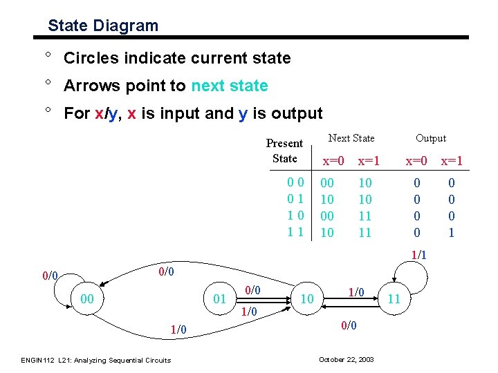
State Diagram ° Circles indicate current state ° Arrows point to next state ° For x/y, x is input and y is output Present State 00 01 10 11 Next State Output x=0 x=1 00 10 10 10 11 11 0 0 0 0 1 1/1 0/0 00 01 1/0 ENGIN 112 L 21: Analyzing Sequential Circuits 0/0 10 1/0 0/0 October 22, 2003 11
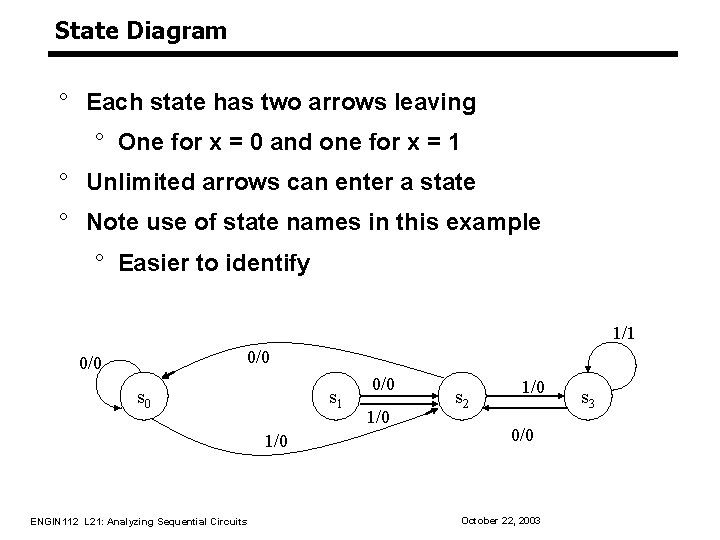
State Diagram ° Each state has two arrows leaving ° One for x = 0 and one for x = 1 ° Unlimited arrows can enter a state ° Note use of state names in this example ° Easier to identify 1/1 0/0 s 0 s 1 1/0 ENGIN 112 L 21: Analyzing Sequential Circuits 0/0 1/0 s 2 1/0 0/0 October 22, 2003 s 3
Flip Flop Input Equations ° Boolean expressions which indicate the input to the flip flops. x Q 1 D 0 D Q Q’ Q Q 0 D D 1 Q 0 Q’ y Q 1 Clk DQ 0 = x. Q 1 DQ 1 = x + Q 0 Format implies type of flop used ENGIN 112 L 21: Analyzing Sequential Circuits October 22, 2003
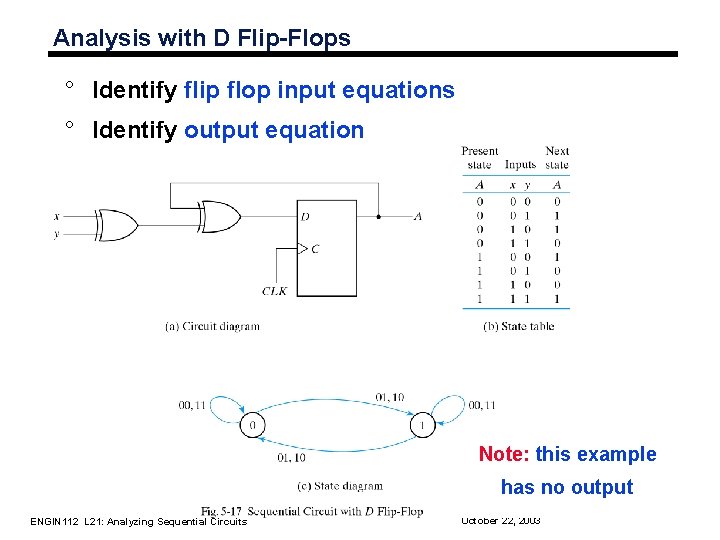
Analysis with D Flip-Flops ° Identify flip flop input equations ° Identify output equation Note: this example has no output ENGIN 112 L 21: Analyzing Sequential Circuits October 22, 2003
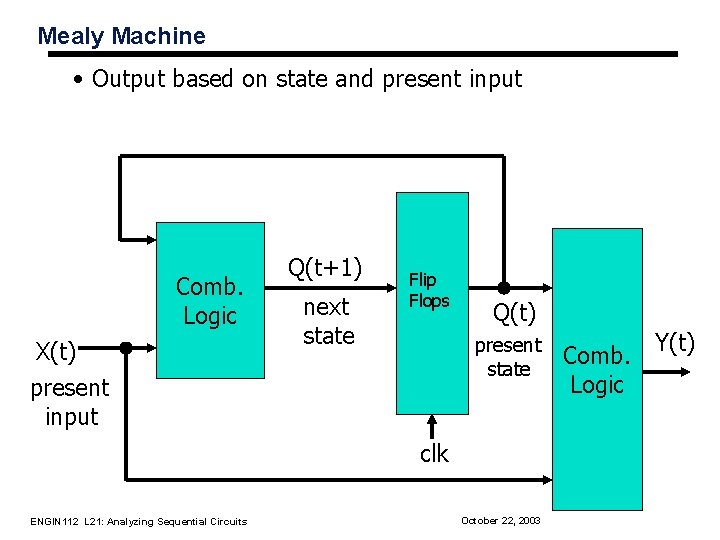
Mealy Machine • Output based on state and present input Comb. Logic X(t) present input Q(t+1) next state Flip Flops Q(t) present state clk ENGIN 112 L 21: Analyzing Sequential Circuits October 22, 2003 Comb. Logic Y(t)
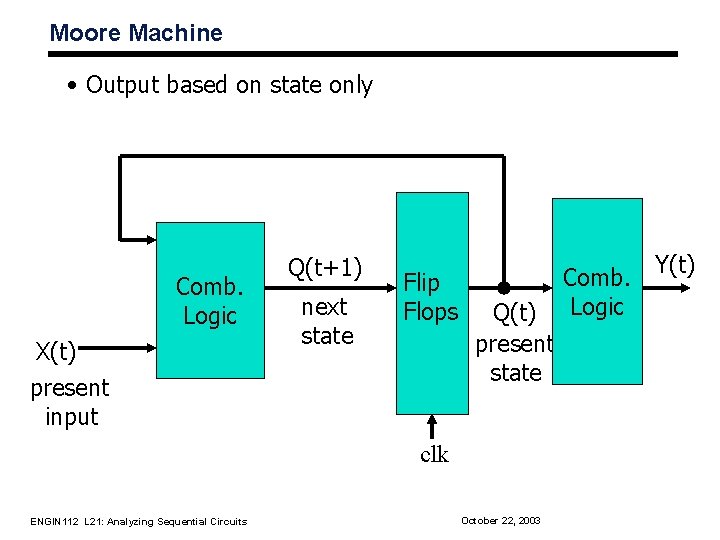
Moore Machine • Output based on state only Comb. Logic X(t) present input Q(t+1) next state Flip Flops Q(t) present state clk ENGIN 112 L 21: Analyzing Sequential Circuits October 22, 2003 Comb. Logic Y(t)
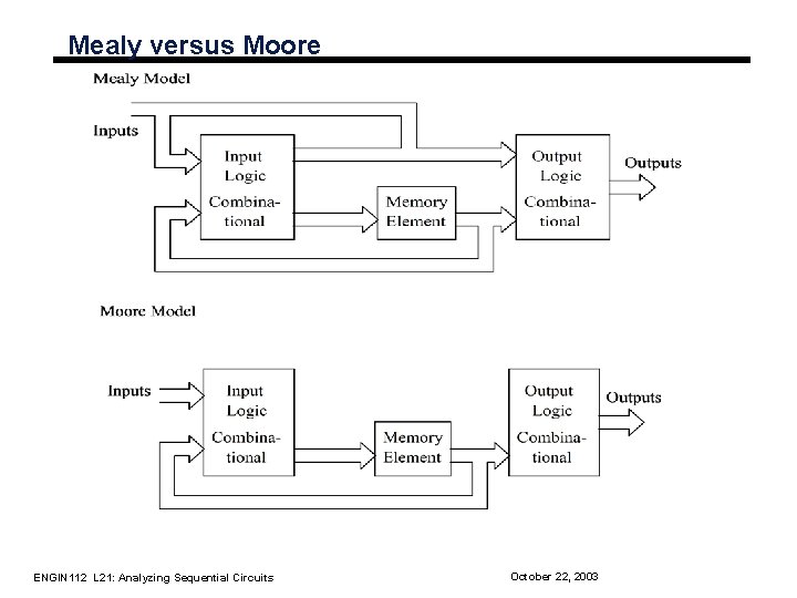
Mealy versus Moore ENGIN 112 L 21: Analyzing Sequential Circuits October 22, 2003
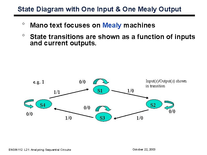
State Diagram with One Input & One Mealy Output ° Mano text focuses on Mealy machines ° State transitions are shown as a function of inputs and current outputs. e. g. 1 S 1 1/1 S 4 0/0 Input(s)/Output(s) shown in transition 0/0 1/0 S 2 0/0 1/0 ENGIN 112 L 21: Analyzing Sequential Circuits 0/0 S 3 1/0 October 22, 2003
State Diagram with One Input & a Moore Output ° Moore machine: outputs only depend on the current state ° Outputs cannot change during a clock pulse if the input variables change ° Moore Machines usually have more states. ° No direct path from inputs to outputs ° Can be more reliable ENGIN 112 L 21: Analyzing Sequential Circuits October 22, 2003
Clocked Synchronous State-machine Analysis – next class Given the circuit diagram of a state machine: 1 Analyze the combinational logic to determine flip-flop input (excitation) equations: Di = Fi (Q, inputs) • The input to each flip-flop is based upon current state and circuit inputs. 2 Substitute excitation equations into flip-flop characteristic equations, giving transition equations: Qi(t+1) = Hi( Di ) 3 From the circuit, find output equations: • Z = G (Q, inputs) The outputs are based upon the current state and possibly the inputs. 4 Construct a state transition/output table from the transition and output equations: • • • Similar to truth table. Present state on the left side. Outputs and next state for each input value on the right side. • Provide meaningful names for the states in state table, if possible. 5 Draw the state diagram which is the graphical representation of state table. ENGIN 112 L 21: Analyzing Sequential Circuits October 22, 2003
Summary ° Flip flops contain state information ° State can be represented in several forms: • State equations • State table • State diagram ° Possible to convert between these forms ° Circuits with state can take on a finite set of values • Finite state machine ° Two types of “machines” • Mealy machine • Moore machine ENGIN 112 L 21: Analyzing Sequential Circuits October 22, 2003