Deployment Diagram Deployment diagrams indicate how the software


- Slides: 13
Deployment Diagram
� Deployment diagrams indicate how the software is to be installed across systems—for example, what will be installed on the server and what will be installed on the admin PCs. � A deployment diagram shows how the finished system will be deployed on one or more machines. A deployment diagram can include all sorts of features such as machines, processes, files and dependencies. � A deployment diagram is used to show the allocation of artifacts to nodes in the physical design of a system. A single deployment diagram represents a view into the artifact structure of a system. During development, we use deployment diagrams to indicate the physical collection of nodes that serve as the platform for execution of our system.
�Layered architecture is an approach to splitting up software into packages. The term refers to breaking up a software application into distinct layers or tiers. These levels are arranged above one another, each serving distinct and separate tasks. Software in one tier may only access software in another tier, according to strict rules. In an OO system, systems analysts create class packages for each tier and populate these with classes that implement the architecture. For example, they might add a class to handle the saving and retrieving of objects from the database. �There a number of approaches to layered architecture : Monolithic (One-tier), Two-tier , Three-tier, N-tier
� In monolithic architecture, these three areas are all bundled together in a single application. Monolithic architecture is often employed on mainframe systems. � The common approach for new systems is to separate the application into various layers, or tiers. In two-tier architecture, there are two layers: a server (a central computer system) and a client (one system at each desk). In the “thin client, fat server” variation on this theme, the presentation logic and minimal business logic reside on the client system; the rest is on the server. In “fat client, thin server, ” the presentation logic and much of the business logic reside on the client. � In three-tier architecture, there are three layers, or subsystems: a client system, loaded with presentation logic; an application server with business logic; and a data server with data logic. � Finally, in N-tier architecture any number (N) of levels is arranged, each serving distinct and separate tasks.
� Any software application can be seen as consisting of three broad areas: � Data logic: The software to manage the data � Business (processing) logic: The software that enacts the business rules � Presentation (interface) logic: The software that manages the presentation of the output (such as screens)
Essentials: The Artifact Notation � An artifact is a physical item that implements a portion of the software design. It is typically software code (executable) but could also be a source file, a document, or another item related to the software code. Artifacts may have relationships with other artifacts, such as a dependency or a composition. � The notation for an artifact consists of a class rectangle containing the name of the artifact.
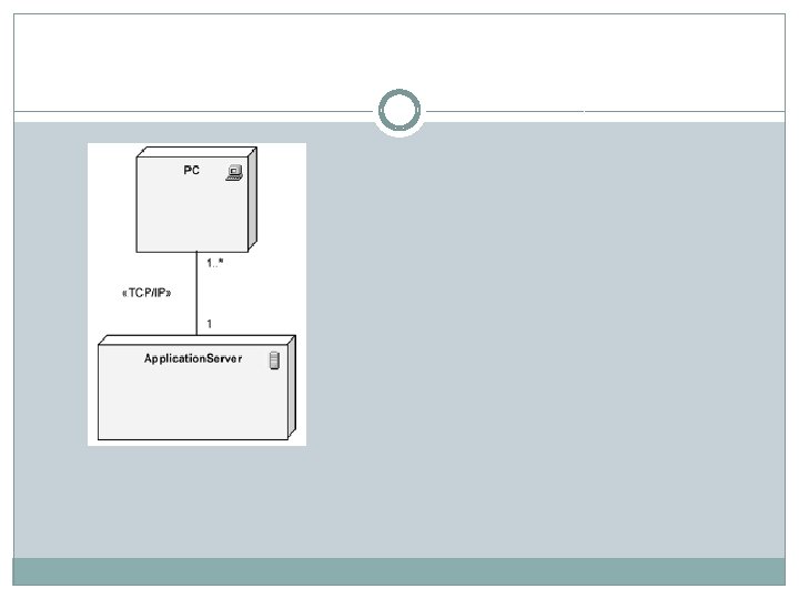
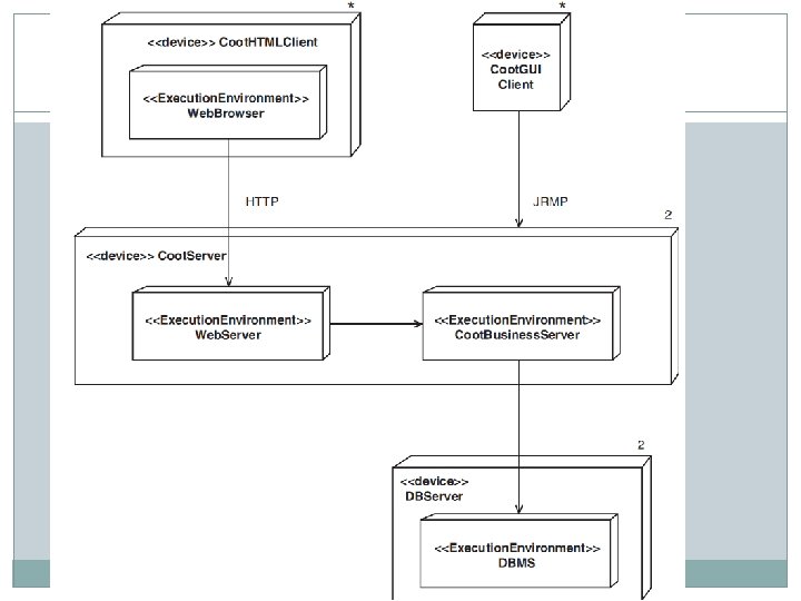
Essentials: The Node Notation � A node is a computational resource, typically containing memory and processing, on which artifacts are deployed for execution. Nodes may contain other nodes to represent complex execution capability; this is shown by nesting or using a composition relationship. There are two types of nodes: devices and execution environments � A device is a piece of hardware that provides computational capabilities, such as a computer, a modem, or a sensor. An execution environment is software that provides for the deployment of specific types of executing artifacts; examples include «database» and «J 2 EE server» . Execution environments are typically hosted by a device. � Nodes communicate with one another, via messages and signals, through a communication path indicated by a solid line. Communication paths are usually considered to be bidirectional, although if a particular connection is unidirectional, an arrow may be added to show the direction. Each communication path may include an optional keyword label, such as «http» or «TCP/IP» , that provides information about the connection. We may also specify multiplicity for each of the nodes connected via a communication path.
Essentials: The Deployment Diagram
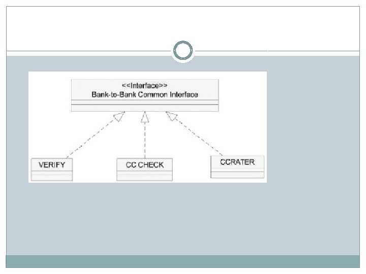
Interfaces � “A named set of operations that characterize the behavior of an element. ” � Developers may also add to the classes introduced by the BA by designing interfaces. An interface acts like a generalized class except that it has no attributes and no process logic; only operation names and standard rules for invoking them are defined. Each class that obeys the interface must conform to the interface’s rule regarding the operations. A class that obeys the interface is said to be a type of the interface. � There a number of ways to indicate an interface in the UML. The simplest way is to use the simple box notation, with the stereotype <<Interface>>. The types are connected to the interface with an arrow that looks like the generalization relationship, except that it is dashed.