UNIT V Package Diagram Component Diagram Deployment Diagram


.")


")

- Slides: 60
UNIT - V Package Diagram, Component Diagram & Deployment Diagram P. P. Mahale
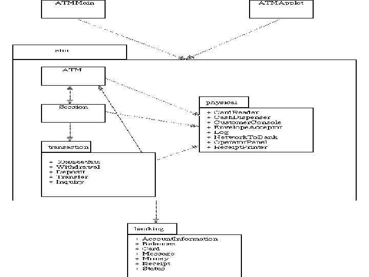
Package diagrams § Packages: - It is general purpose mechanism for organizing modeling elements into group. - Manipulate a group - Control visibility of elements so that some things are visible outside the package while other are hidden - Well designed packages group elements that are semantically close and tend to change together - package is shown as a tabbed folder, usually including only its name and, sometimes, its contents
• There also variations, such as frameworks, models, and subsystems (kinds of packages). • name : -Every package must have name , name is textual string • Path name is package name prefixed by name of package in which that package lives
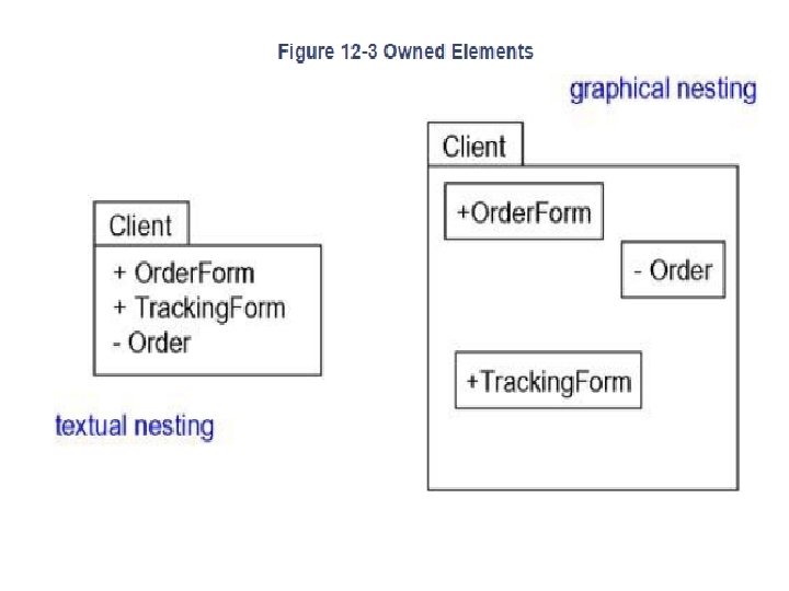
• Owned Elements • A package may own other elements, including classes, interfaces, components, nodes, collaborations, use cases, diagrams, and even other packages. • Owning is a composite relationship, which means that the element is declared in the package. • If the package is destroyed, the element is destroyed. Every element is uniquely owned by exactly one package.
Airport check-in and security screening business model
• Package forms a namespace, which means that elements of the same kind must be named uniquely within the context of its enclosing package • Elements of different kinds may have the same name within a package • Packages may own other packages
• Visibility • Element owned by a package is public, which means that it is visible to the contents of any package that imports the element's enclosing package. - Conversely, protected elements can only be seen by children - Private elements cannot be seen outside the package in which they are declared - Specify visibility of an element owned by a package by prefixing the element's name with an appropriate visibility symbol
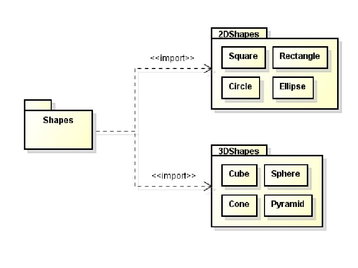
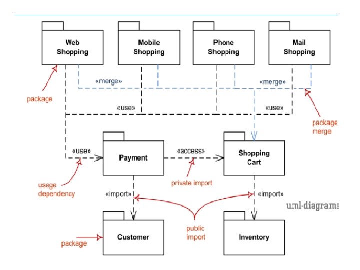
• Importing and Exporting - If A's package imports B's package, A can now see B, although B cannot see A. - Importing grants a one-way permission for the elements in one package to access the elements in another package. - In the UML, you model an import relationship as a dependency adorned with the stereotype import. - Two stereotypes apply here import and access
- Import adds the contents of the target to the source's namespace, - Access does not add the contents of the target, and so you do have to qualify their names. - Import and access dependencies are not transitive - If an element is visible within a package, it is visible within all packages nested inside the package. - Nested packages can see everything that their containing packages can see.
- The public parts of a package are called its exports. - The keyword «import» is shown near the dashed arrow if the visibility of import is public while the keyword «access» is used to indicate private visibility • For example, in Figure the package GUI exports two classes, Window and Form. Event. Handler is not exported by GUI; Event. Handler is a protected part of the package.
Private import of Presentation package and public import of Domain package Web Application imports Presentation package.
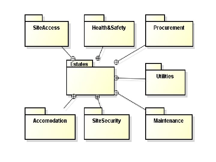
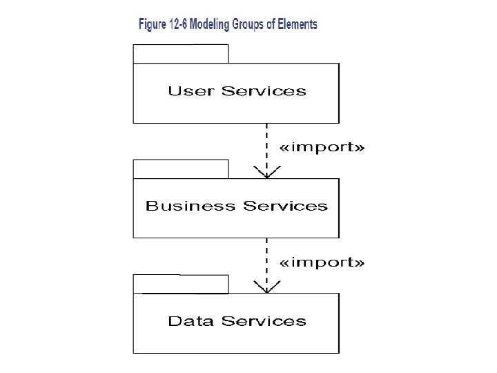
Common Modeling Techniques 1. Modeling Groups of Elements - Common purpose for which you'll use packages is to organize modeling elements into groups that you can name and manipulate as a set - Use packages to group different kinds of elements - To model groups of elements, • Scan the modeling elements in a particular architectural view and look for clumps defined by elements that are conceptually or semantically close to one another.
• Surround each of these clumps in a package. • For each package, distinguish which elements should be accessible outside the package. Mark them public, and all others protected or private. When in doubt, hide the element. • Explicitly connect packages that build on others via import dependencies. • In the case of families of packages, connect specialized packages to their more general part via generalizations.
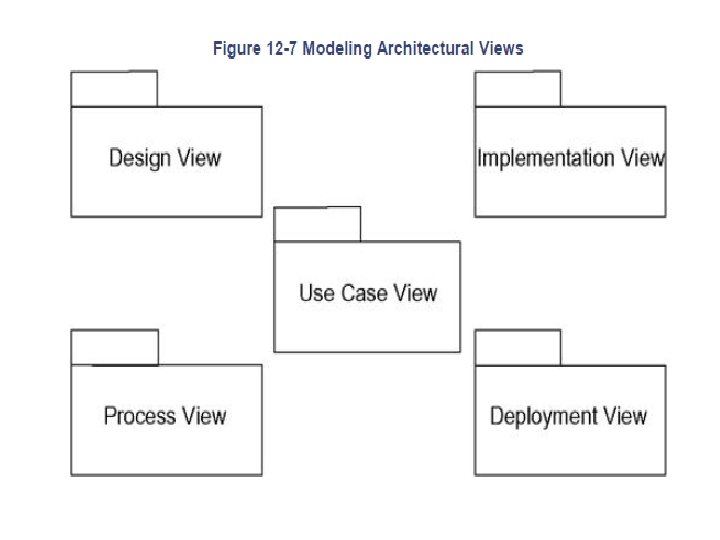
2. Modeling Architectural Views • Using packages to group related elements is important; you can't develop complex models without doing so. • This approach works well for organizing related elements, such as classes, interfaces, components, nodes, and diagrams • Use packages to model the views of an architecture. • A view is a projection into the organization and structure of a system, focused on a particular aspect of that system.
• To model architectural views: - Identify the set of architectural views that are significant in the context of your problem. In practice, this typically includes a design view, a process view, an implementation view, a deployment view, and a use case view. - Place the elements (and diagrams) that are necessary and sufficient to visualize, specify, construct, and document the semantics of each view into the appropriate package. - As necessary, further group these elements into their own packages. - There will typically be dependencies across the elements in different views. So, in general, let each view at the top of a system be open to all others at that level.
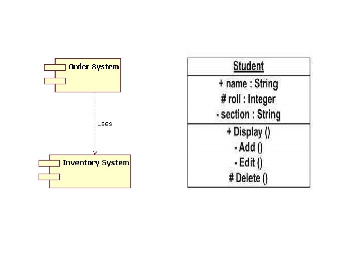
Component diagrams • Important building block in modeling the physical aspects of a system. • A component is a physical and replaceable part of a system that conforms to and provides the realization of a set of interfaces. • Model the physical things that may reside on a node, such as executable, libraries, tables, files, and documents. A component typically represents the physical packaging of otherwise logical elements, such as classes, interfaces, and collaborations. • UML provides a graphical representation of a component as
q Terms and Concepts § Names • Every component must have a name that distinguishes it from other components. • A name is a textual string. That name alone is known as a simple name; a path name is the component name prefixed by the name of the package in which that component lives
§ Components and Classes • In many ways, components are like classes: Both have names; both may realize a set of interfaces; both may participate in dependency, generalization, and association relationships; • both may be nested; both may have instances; both may be participants in interactions. • However, there are some significant differences between components and classes.
1. Classes represent logical abstractions; components represent physical things that live in the world In short, components may live on nodes, classes may not. 2. Components represent the physical packaging of otherwise logical components and are at a different level of abstraction. 3. Classes may have attributes and operations directly. In general, components only have operations that are reachable only through their interfaces.
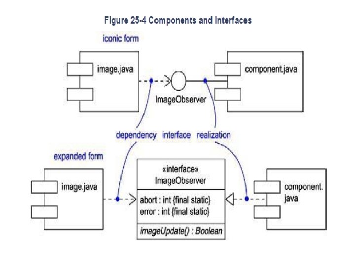
§ Components and Interfaces • Interface is a collection of operations that are used to specify a service of a class or a component • Component that accesses the services of the other component through the interface is connected to the interface using a dependency relationship. • An interface that a component realizes is called an export interface, meaning an interface that the component provides as a service to other components. • A component may provide many export interfaces. The interface that a component uses is called an import interface, meaning an interface that the component conforms to and so builds on. • A component may both import and export interfaces.
§ Kinds of Components : Three kinds of components 1. Deployment components. These are the components necessary and sufficient to form an executable system, such as dynamic libraries (DLLs) and executables (EXEs). 2. Work product components. These components are essentially the residue of the development process, consisting of things such as source code files and data files from which deployment components are created. These components do not directly participate in an executable system but are the work products of development that are used to create the executable system.
3. Execution components. These components are created as a consequence of an executing system § Organizing Components • You can organize components by grouping them in packages in the same manner in which you organize classes. • Organize components by specifying dependency, generalization, association (including aggregation), and realization relationships among them.
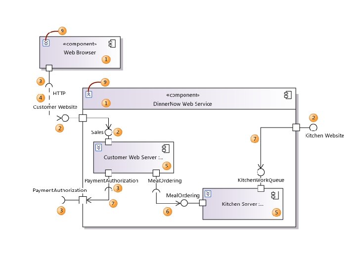
§ Common Properties • Name and graphical contents that are a projection into a model. What distinguishes a component diagram from all other kinds of diagrams is its particular content § Contents - Component diagrams commonly contain • Components • Interfaces • Dependency, relationships generalization, • Notes and constraints association, and realization
§ Common Uses - To model the static implementation view of a system 1. To model source code 2. To model executable releases 3. To model physical databases 4. To model adaptable systems
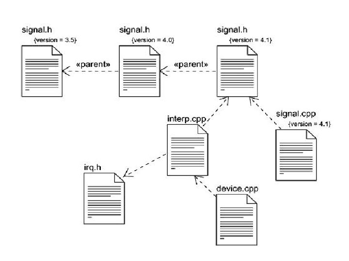
q Common Modeling Techniques § Modeling Source Code - To model a system's source code, • Either by forward or reverse engineering, identify the set of source code files of interest and model them as components stereotyped as files. • For larger systems, use packages to show groups of source code files. • Consider exposing a tagged value indicating such information as the version number of the source code file, its author, and the date it was last changed. Use tools to manage the value of this tag. • Model the compilation dependencies among these files using dependencies. Again, use tools to help generate and manage these dependencies.
§ Modeling an Executable Release -To model an executable release, • Identify the set of components you'd like to model • Consider the stereotype of each component in this set • For each component in this set, consider its relationship to its neighbors
• • § Modeling a Physical Database To model a physical database, Identify the classes in your model that represent your logical database schema. Select a strategy for mapping these classes to tables. To visualize, specify, construct, and document your mapping, create a component diagram that contains components stereotyped as tables. Where possible, use tools to help you transform your logical design into a physical design.
§ Modeling Adaptable Systems To model an adaptable system, • Consider the physical distribution of the components that may migrate from node to node. You can specify the location of a component instance by marking it with a location tagged value, which you can then render in a component diagram • If you want to model the actions that cause a component to migrate, create a corresponding interaction diagram that contains component instances.
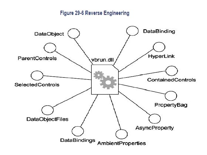
§ Forward and Reverse Engineering - To forward engineer a component diagram • For each component, identify the classes or collaborations that the component implements. • Choose the target for each component. Your choice is basically between source code • Use tools to forward engineer your models. - To reverse engineer a component diagram, • Choose the target you want to reverse engineer • Using a tool, point to the code you'd like to reverse engineer. • Using your tool, create a component diagram by querying the model
DEPLOYMENT DIAGRAMS - Nodes, are an important building block in modeling the physical aspects of a system. - A node is a physical element that exists at run time and represents a computational resource, generally having at least some memory and, often, processing capability. - Use nodes to model the topology of the hardware on which your system executes. - A node typically represents a processor or a device on which components may be deployed.
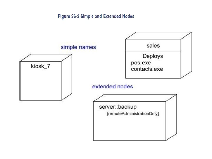
• UML provides a graphical representation of node, as Figure § Terms and Concepts • Names - Every node must have a name that distinguishes it from other nodes. A name is a textual string. - That name alone is known as a simple name; a path name is the node name prefixed by the name of the package in which that node lives.
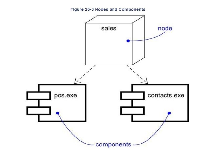
§ Nodes and Components • Nodes are a lot like components: Both have names; both may participate in dependency, generalization, and association relationships; both may be nested; both may have instances • both may be participants in interactions. • Differences between nodes and components. 1. Components are things that participate in the execution of a system nodes are things that execute components. 2. Components represent the physical packaging of otherwise logical elements; nodes represent the physical deployment of components.
• • § • § Organizing Nodes Organize nodes by grouping them in packages in the same manner in which you can organize classes and components Organize nodes by specifying dependency, generalization, and association (including aggregation) relationships among them. Connections Association represents a physical connection among nodes, nodes such as an Ethernet connection, a serial line, or a shared bus, as Fig.
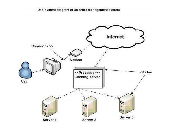
§ Terms and Concepts • Deployment diagram is a diagram that shows the configuration of run time processing nodes and the components that live on them. • Graphically, a deployment diagram is a collection of vertices and arcs § Common Properties § Contents • Deployment diagrams commonly contain • Nodes • Dependency and association relationships • Notes and constraints.
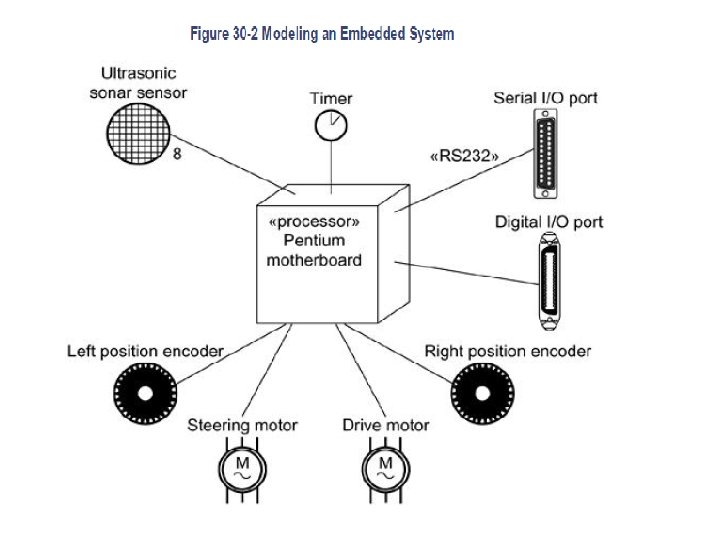
§ Common Modeling Techniques • Modeling an Embedded System To model an embedded system, • Identify the devices and nodes that are unique to your system. Identify • Provide visual cues, especially for unusual devices, by using the UML's extensibility mechanisms to define system-specific stereotypes with appropriate icons • Model the relationships among these processors and devices in a deployment diagram. • As necessary, expand on any intelligent devices by modeling their structure with a more detailed deployment diagram. more detailed
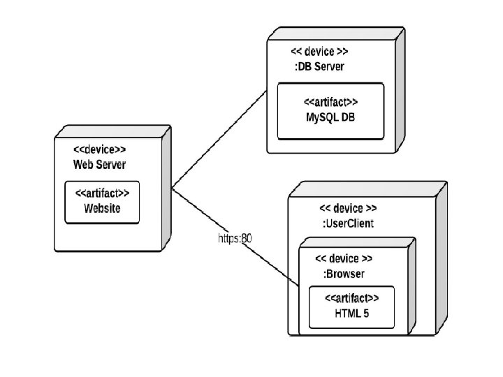
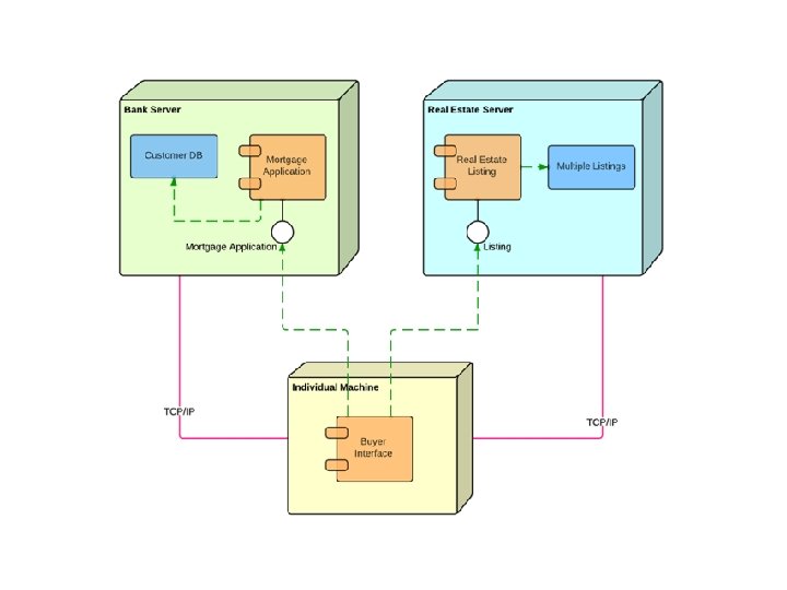
§ Modeling a Client/Server System To model a client/server system, • Identify the nodes that represent your system's client and server processors. • Highlight those devices that are germane to the behavior of your system germane • Provide visual cues for these processors and devices via stereotyping. • Model the topology of these nodes in a deployment diagram. Similarly, specify the relationship between the components in your system's implementation view and the nodes in your system's deployment view. implementation view
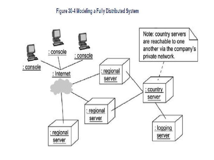
§ Modeling a Fully Distributed System To model a fully distributed system, • Identify the system's devices and processors as for simpler client/server systems. • If you need to reason about the performance of the system's network or the impact of changes to the network, be sure to model these communication devices to the level of detail sufficient to make these assessments. • Pay close attention to logical groupings of nodes, which you can specify by using packages. • Model these devices and processors using deployment diagrams Model • If you need to focus on the dynamics of your system, introduce use case diagrams to specify the kinds of behavior
§ Forward and Reverse Engineering • Forward engineering (the creation of code from models) can do with deployment diagrams. • After specifying the physical distribution of components across the nodes in a deployment diagram, it is possible to use tools that then push these components out to the real world. For system administrators, using the UML in this way helps you visualize what can be a very complicated task. • Reverse engineering (the creation of models from code) from the real world back to deployment diagrams is of tremendous value, especially for fully distributed systems that are under constant change. • You'll want to supply a set of stereotyped nodes that speak the language of your system's network administrators.
• To reverse engineer a deployment diagram • Choose the target that you want to reverse engineer. In some cases, you'll want to sweep across your entire network; in others, you can limit your search. • Choose also the fidelity of your reverse engineering. In some cases, it's sufficient to reverse engineer just to the level of all the system's processors; in others, you'll want to reverse engineer the system's networking peripherals, as well. • Use a tool that walks across your system, discovering its hardware topology. Record that topology in a deployment model.