Construction of a Digital Hadron Calorimeter with Resistive


- Slides: 22

Construction of a Digital Hadron Calorimeter with Resistive Plate Chambers Lei Xia Argonne National Laboratory

RPC DHCAL Collaboration Argonne Boston University Mc. Gill University Burak Bilki Carol Adams Mike Anthony Tim Cundiff Eddie Davis Pat De Lurgio Gary Drake Kurt Francis Robert Furst Vic Guarino Bill Haberichter Andrew Kreps Zeljko Matijas José Repond Jim Schlereth Frank Skrzecz (Jacob Smith) (Daniel Trojand) Dave Underwood Ken Wood Lei Xia Allen Zhao John Butler Eric Hazen Shouxiang Wu François Corriveau Daniel Trojand RPC 2012 UTA Fermilab Alan Baumbaugh Lou Dal Monte Jim Hoff Scott Holm Ray Yarema Jacob Smith Jaehoon Yu IIT Guang Yang Daniel Kaplan IHEP Beijing Qingmin Zhang University of Iowa Burak Bilki Edwin Norbeck David Northacker Yasar Onel RED = Electronics Contributions GREEN = Mechanical Contributions Yellow = Students BLACK = Physicist

Motivation: physics at the next lepton collider – Physics Benchmarks for the ILC Detectors Required: excellent Jet energy/mass resolution Solution: Particle Flow Algorithm (PFA) RPC 2012

Need new approach Particle Flow Algorithms KL The idea… ECAL Charged particles Tracker γ measured with the Neutral particles π+ Calorimeter Particles in jets Fraction of energy Measured with Resolution [σ2] Charged 65 % Tracker Negligible Photons 25 % ECAL with 15%/√E 0. 072 Ejet Neutral Hadrons 10 % ECAL + HCAL with 50%/√E 0. 162 Ejet Confusion HCAL Required for 30%/√E 18%/√E ≤ 0. 242 Ejet Requirements for detector system → → → Need excellent tracker and high B – field Large RI of calorimeter Calorimeter inside coil Calorimeter as dense as possible (short X 0, λI) Calorimeter with extremely fine segmentation → Single particle energy resolution not critical RPC 2012 thin active medium Opens up new possibilities

Digital Hadron Calorimeter (DHCAL) and Choice of active medium § Requirement of PFA hadron calorimeter – Extremely fine segmentation (~1 x 1 cm 2 readout cell) simple hit counting provide sufficient energy resolution 1 bit readout/Digital Hadron Calorimeter (DHCAL) – DHCAL counting charged particles in hadronic showers (instead of measuring d. E/dx in the active medium) the active medium can have poor, or even no d. E/dx resolution – Thin active medium, embedded readout – Cost – … § What RPC can offer – Good position resolution great for fine segmentation – Excellent efficiency for charged particles great for counting charged particles – Large charge fluctuation for single MIP no d. E/dx resolution, poor particle counting on single pad but this is exactly NOT needed for a DHCAL – Can be made very thin – Low cost – … § RPC is a perfect choice for a Digital Hadron Calorimeter! RPC 2012

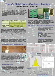
1 m 3 – Digital Hadron Calorimeter Physics Prototype Description Readout of 1 x 1 cm 2 pads with one threshold (1 -bit) → Digital Calorimeter 38 layers in DHCAL and 14 in Tail Catcher, each ~ 1 x 1 m 2 Absorber: 18 mm Fe + 2 mm Cu in DHCAL, thicker Fe plates in Tail Catcher Each layer with 3 RPCs, each 32 x 96 cm 2 ~480, 000 readout channels Purpose Validate DHCAL concept Gain experience running large RPC systems Measure hadronic showers in great detail Validate hadronic shower models (Geant 4) Status Critical for PFA validation Started construction in 2008 Completed in January 2011 Test beam runs started in Oct. 2010 at Fermilab More test beam runs in 2011 Analysis on-going RPC 2012 6

RPC Construction RPC design Pad board Glass Frame 2 – glass RPCs (chosen for construction) 1 – glass RPCs (developed at Argonne) Gas gap size 1. 1 mm Well arranged gas flow (by fishing line + sleeve spacer) Total RPC thickness < 3. 4 mm Dead area ~5% (frame ~3%, spacer ~2%) RPC production ~114 for DHCAL + 42 for TCMT + spares at the end, produced ~ 205 RPC’s Resistive paint spraying • Uses two-component artist paint • Built dedicated spraying booth RPC 2012 plates with value 1 – 5 MΩ/□ • Accept • Achieved a yield of ~60% overall Gap assembly • Developed precision cutting/gluing fixtures • Production rate 1 RPC/day/tech 7

Quality Assurance Pressure tests All RPC’s are tested with 0. 3 inch of water pressure Gap size measurement Thickness of 1 st batch RPC’s measured along the edges (Gap size away from the edges is assured by spacers) Gap sizes along edges vary within 0. 1 mm Corners typically thicker (up to 0. 3 mm, but limited effect) HV tests ALL RPC’s tested up to 7. 0 k. V before placing readout board on top (nominal operating voltage is 6. 3 k. V) Cosmic ray test 9 of the 1 st batch RPC’s were tested on a cosmic ray test stand for performance (efficiency, multiplicity, uniformity) All other RPC’s were later tested in vertical position with cosmic rays, after assembled into cassettes Overall yield: ~95% RPC 2012 8

Design consideration for readout system § System is built around a custom ASIC (DCAL chip) – Designed to handle huge number of channels + low channel density (1 cm 2 pad, 1 m 2 planes, 38+14 planes 480 K channels) – 64 ch, handling 8 x 8 RPC active area § System tailored for test beam / prototype tests, NOT for real colliding beam detector – Facilitates all possible tests (test beam, cosmic ray test, noise runs, system diagnostics, etc) – Avoided cutting-edge technology and fancy functionality • Didn’t optimize for minimum power consumption, minimum data links, minimum thickness, etc. – Compromises aimed at proving detector concept key in getting system up quickly and running reliably § Two basic running mode – External triggering mode primary method for beam events, also used for cosmic ray test • 20 -stage pipeline 2μs latency @ 100 ns clock cycle • Deadtimeless readout (within rate limit) – Self triggering mode primary method for noise runs, also used for cosmic ray, beam runs RPC 2012 • Powerful running mode for monitoring RPC condition • Equally powerful for cosmic ray running and some beam running as well

Readout system overview VME Interface Data Collectors – Need 10 master IN Ext. Trig In Data Concentrator Chambers – 3 per plane To PC Front End Board with DCAL Chips & Integrated DCON VME Interface 6 U VME Crate Timing Module -Double Width -- 16 Outputs Data Collectors – Need 10 master IN Ext. Trig In To PC Communication Link - 1 per Front-End Bd 6 U VME Crate Timing Module -Double Width -- 16 Outputs Square Meter Plane RPC 2012 10

The DCAL Chip Developed by FNAL and Argonne 64 channels High gain (GEMs, micromegas…) with minimum threshold ~ 5 f. C Low gain (RPCs) with minimum thrshold ~ 30 f. C Threshold Hits/100 tries Input Set by 8 – bit DAC (up to ~600 f. C) Common to 64 channels Readout Triggerless (noise measurements) Triggered (cosmic, test beam) Threshold (DAC counts) Versions DCAL I: initial round (analog circuitry not optimized) DCAL II: some minor problems (used in vertical slice test) DCAL III: no identified problems (final production: used in current test beam) Production of DCAL III 11 wafers, 10, 300 chips, fabricated, packaged, tested RPC 2012 Threshold (DAC counts) 11 11

Front. End/DCON board + Pad board ASIC Front-End PCB Communication Link Conductive Epoxy Glue Pad Board Signal pads Mylar Resistive paint 0. 85 mm glass 1. 2 mm gas gap Fishing line spacers Resistive paint Mylar 8. 6 mm HV 1. 1 mm glass Aluminum foil § § § Build FE and pad boards separately to avoid blind and buried vias (cost and feasibility issue) Each board contains 1536 channels and 24 ASICs The data concentrator is implemented into the same board Glue the two boards together with conductive epoxy FE board need to pass computer test before gluing – Extensive tests (S-curves, noise rates…) – 3 – 6 hours/board – Accepted boards with less than 4/1536 dead channels RPC 2012 12

Back end electronics 1. Timing and Trigger Module (TTM) 2. Data Collector DCOL Power supply systems 1. Low voltage system 2. High voltage system Gas System RPC 2012 13

Cassette Assembly - FEB’s are placed onto RPC’s directly (no gluing), positioning and contact is assured by pressure asserted from cassette - Cassette is compressed horizontally with a set of 4 (Badminton) strings - Strings are tensioned to ~20 lbs each, very few broken strings Cassette Testing - Cassettes were tested with CR before shipping to test beam 38+14 cassettes assembled RPC 2012 14

Digital calorimeter: will it work? § During the time we were busy with the DHCAL construction (2010), Richard Wigmans, who wrote a well-known book on calorimeter, claimed at a calorimeter conference: “ ‘Digital’ calorimetry was tried and abandoned for good reason (1983) ” § Unfortunately, this was said too late – we were very close to finishing the DHCAL construction § Even more unfortunately, it only took us a short while in the test beam to prove him wrong! RPC 2012

The DHCAL in the Test Beam Run III Run IV Run V Fermilab test beam run dates DHCAL layers RPC_TCMT layers SC_TCMT layers Total RPC layers Total layers Readout channels 10/14/2010 – 11/3/2010 38 0 16 38 54 350, 208+320 1/7/2011 – 1/10/2011 38 0 8 38 46 350, 208+160 1/11/2011 – 1/20/2011 38 4 8 42 50 387, 072+160 1/21/2011 – 2/4/2011 38 9 6 47 53 433, 152+120 2/5/2011 – 2/7/2011 38 13 0 51 51 470, 016+0 4/6/2011 – 5/11/2011 38 14 0 52 52 479, 232+0 5/26/2011 – 6/28/2011 38 14 0 52 52 479, 232+0 11/2/2011 – 12/6/2011 50 0 0 50 50 460800 ~ 480 K readout channels ~ 35 M events RPC 2012 More test beam in 2012, at CERN DHCAL Tail Catcher (TCMT)

RPC 2012 17

First beam: muons One muon Three muons Four muons RPC 2012 A lot of muons 18

Next: pions 60 Ge. V pions measured in DHCal RPC 2012 19

And also positrons 32 Ge. V 25 Ge. V 20 Ge. V 16 Ge. V RPC 2012 12 Ge. V 20

And occasionally, neutral hadron RPC 2012 21

Summary § § § § The construction of the DHCAL prototype (+Tail Catcher) is complete Test beam at Fermilab started in October 2010 Had 5 successful test beam campaigns in 2010/11 DHCAL prototype (+Tail Catcher) works extremely well A lot of good data collected, analysis is on-going First look at data is very encouraging! More test beam/more data is on the way – 2012 : At CERN with Tungsten absorber For more details of the DHCAL performance and preliminary physics results Please see: • Next talk, by Jose Repond (Analysis of DHCAL Events) • Poster, by B. Bilki (Response of the DHCAL to Hadrons and Positrons) RPC 2012 22
 Hadron calorimeter
 Coffee cup calorimeter formula
 Capacity to do work is called
 Coffee cup calorimeter vs bomb calorimeter
 Digital calorimeter
 Hadron collider
 Hadron
 Hadron
 Hadron collider
 Resistive displacement sensor
 Resistive index definition
 Vdc formula for half wave rectifier
 Inverter loading ratio
 Isokinetic exercise
 Resistive circuit analysis
 Pure resistive circuit
 Resistive switching
 Nmos inverter with resistive load
 Resistive soil moisture sensor working principle
 Purely resistive circuit
 Resistive linear transducer
 Specific heat equation units
 Parr calorimeter
