Chapter 31 Alternating Current Power Point Lectures for
- Slides: 18
Chapter 31 Alternating Current Power. Point® Lectures for University Physics, Twelfth Edition – Hugh D. Young and Roger A. Freedman Lectures by James Pazun Copyright © 2008 Pearson Education Inc. , publishing as Pearson Addison-Wesley
Goals for Chapter 31 • To introduce phasors and alternating current • To study voltage, current, and phase angle • To consider resistance and reactance • To introduce impedance and its application to the L-R-C series circuit • To consider power in AC circuits • To see resistance in AC circuits • To apply AC knowledge to transformers Copyright © 2008 Pearson Education Inc. , publishing as Pearson Addison-Wesley
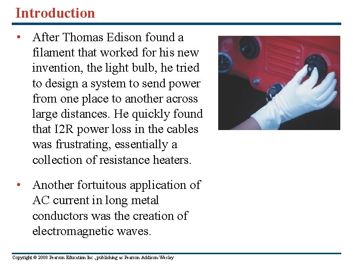
Introduction • After Thomas Edison found a filament that worked for his new invention, the light bulb, he tried to design a system to send power from one place to another across large distances. He quickly found that I 2 R power loss in the cables was frustrating, essentially a collection of resistance heaters. • Another fortuitous application of AC current in long metal conductors was the creation of electromagnetic waves. Copyright © 2008 Pearson Education Inc. , publishing as Pearson Addison-Wesley
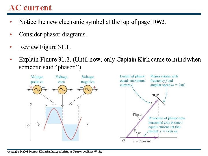
AC current • Notice the new electronic symbol at the top of page 1062. • Consider phasor diagrams. • Review Figure 31. 1. • Explain Figure 31. 2. (Until now, only Captain Kirk came to mind when someone said “phasor. ”) Copyright © 2008 Pearson Education Inc. , publishing as Pearson Addison-Wesley
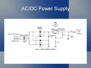
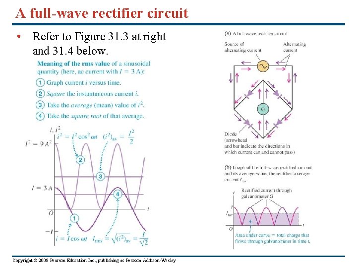
A full-wave rectifier circuit • Refer to Figure 31. 3 at right and 31. 4 below. Copyright © 2008 Pearson Education Inc. , publishing as Pearson Addison-Wesley
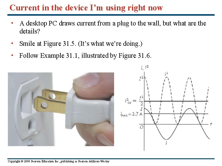
Current in the device I’m using right now • A desktop PC draws current from a plug to the wall, but what are the details? • Smile at Figure 31. 5. (It’s what we’re doing. ) • Follow Example 31. 1, illustrated by Figure 31. 6. Copyright © 2008 Pearson Education Inc. , publishing as Pearson Addison-Wesley
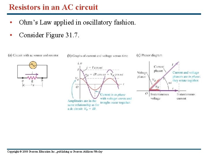
Resistors in an AC circuit • Ohm’s Law applied in oscillatory fashion. • Consider Figure 31. 7. Copyright © 2008 Pearson Education Inc. , publishing as Pearson Addison-Wesley
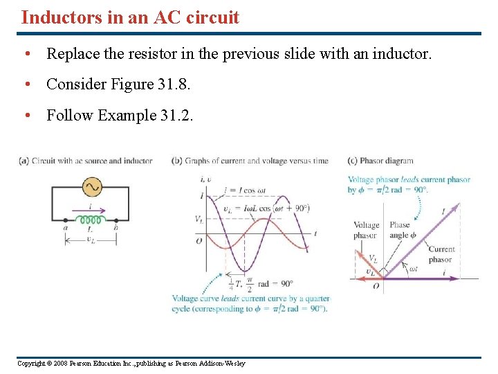
Inductors in an AC circuit • Replace the resistor in the previous slide with an inductor. • Consider Figure 31. 8. • Follow Example 31. 2. Copyright © 2008 Pearson Education Inc. , publishing as Pearson Addison-Wesley
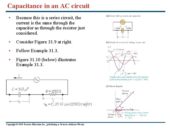
Capacitance in an AC circuit • Because this is a series circuit, the current is the same through the capacitor as through the resistor just considered. • Consider Figure 31. 9 at right. • Follow Example 31. 3. • Figure 31. 10 (below) illustrates Example 31. 3. Copyright © 2008 Pearson Education Inc. , publishing as Pearson Addison-Wesley
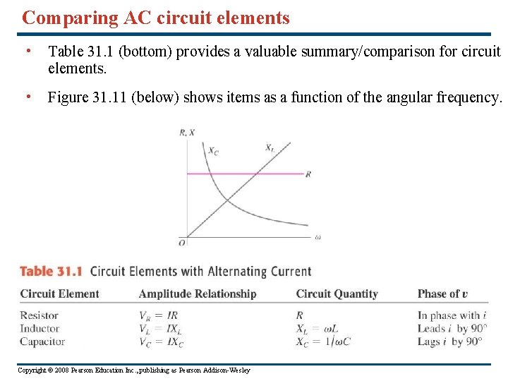
Comparing AC circuit elements • Table 31. 1 (bottom) provides a valuable summary/comparison for circuit elements. • Figure 31. 11 (below) shows items as a function of the angular frequency. Copyright © 2008 Pearson Education Inc. , publishing as Pearson Addison-Wesley
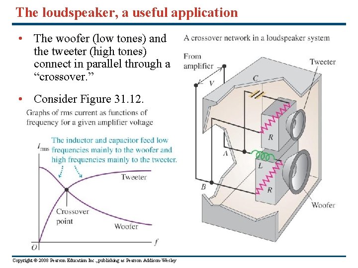
The loudspeaker, a useful application • The woofer (low tones) and the tweeter (high tones) connect in parallel through a “crossover. ” • Consider Figure 31. 12. Copyright © 2008 Pearson Education Inc. , publishing as Pearson Addison-Wesley
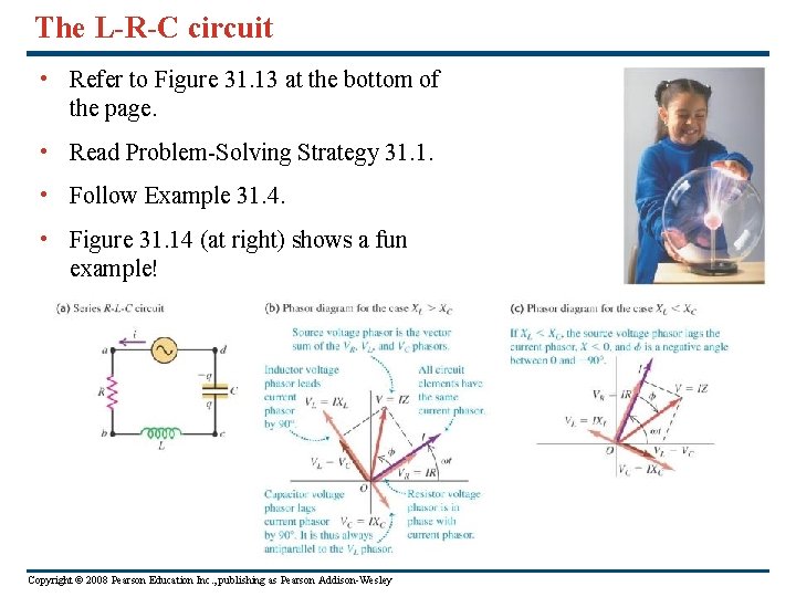
The L-R-C circuit • Refer to Figure 31. 13 at the bottom of the page. • Read Problem-Solving Strategy 31. 1. • Follow Example 31. 4. • Figure 31. 14 (at right) shows a fun example! Copyright © 2008 Pearson Education Inc. , publishing as Pearson Addison-Wesley
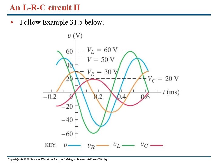
An L-R-C circuit II • Follow Example 31. 5 below. Copyright © 2008 Pearson Education Inc. , publishing as Pearson Addison-Wesley
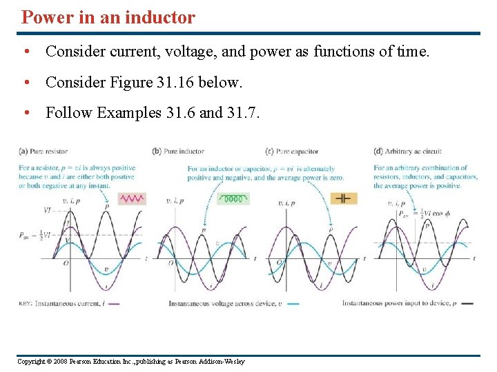
Power in an inductor • Consider current, voltage, and power as functions of time. • Consider Figure 31. 16 below. • Follow Examples 31. 6 and 31. 7. Copyright © 2008 Pearson Education Inc. , publishing as Pearson Addison-Wesley
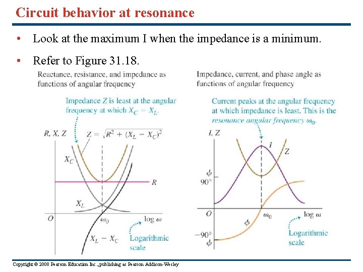
Circuit behavior at resonance • Look at the maximum I when the impedance is a minimum. • Refer to Figure 31. 18. Copyright © 2008 Pearson Education Inc. , publishing as Pearson Addison-Wesley
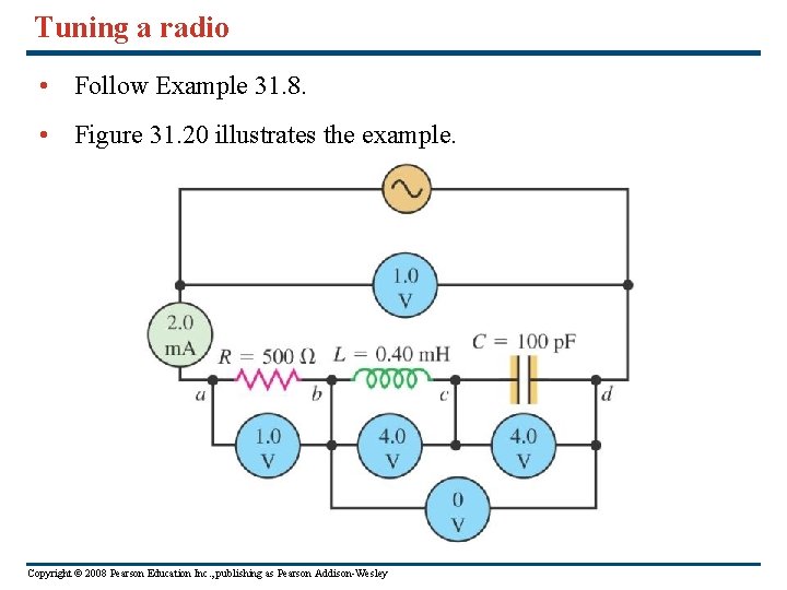
Tuning a radio • Follow Example 31. 8. • Figure 31. 20 illustrates the example. Copyright © 2008 Pearson Education Inc. , publishing as Pearson Addison-Wesley
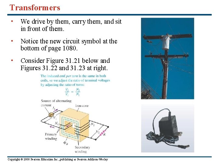
Transformers • We drive by them, carry them, and sit in front of them. • Notice the new circuit symbol at the bottom of page 1080. • Consider Figure 31. 21 below and Figures 31. 22 and 31. 23 at right. Copyright © 2008 Pearson Education Inc. , publishing as Pearson Addison-Wesley
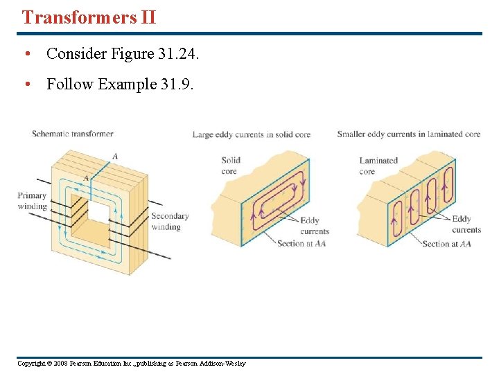
Transformers II • Consider Figure 31. 24. • Follow Example 31. 9. Copyright © 2008 Pearson Education Inc. , publishing as Pearson Addison-Wesley