Challenges in Power Systems State Estimation Lamine Mili
- Slides: 24
Challenges in Power Systems State Estimation Lamine Mili Virginia Tech Alexandria Research Institute 1
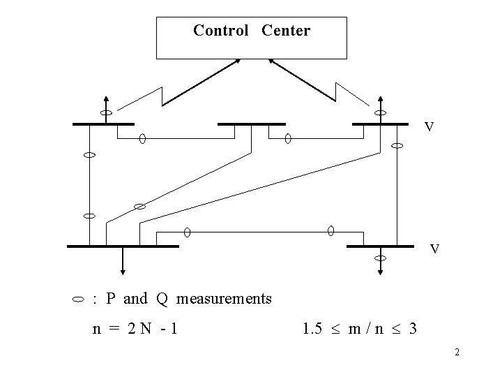
Control Center V V : P and Q measurements n = 2 N -1 1. 5 m / n 3 2
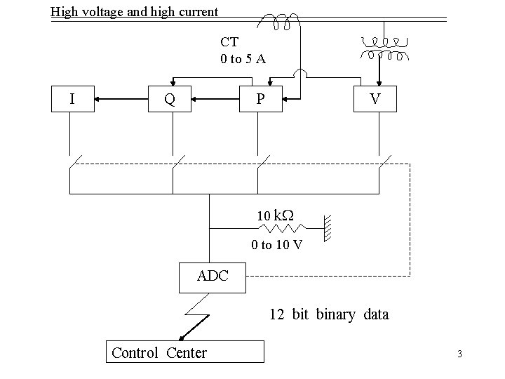
High voltage and high current CT 0 to 5 A I Q P V 10 k. W 0 to 10 V ADC 12 bit binary data Control Center 3
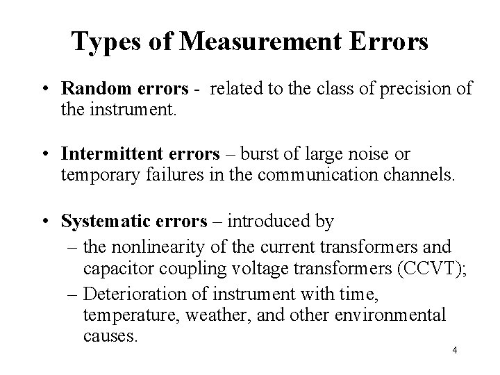
Types of Measurement Errors • Random errors - related to the class of precision of the instrument. • Intermittent errors – burst of large noise or temporary failures in the communication channels. • Systematic errors – introduced by – the nonlinearity of the current transformers and capacitor coupling voltage transformers (CCVT); – Deterioration of instrument with time, temperature, weather, and other environmental causes. 4
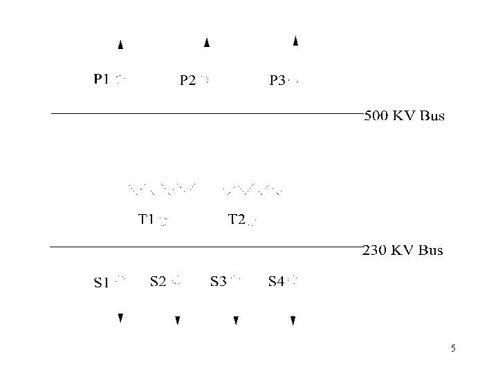
5
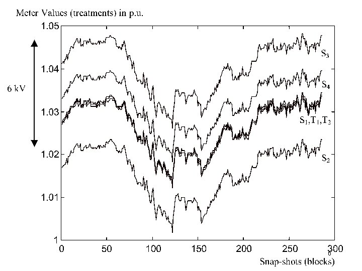
6
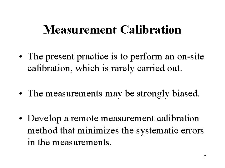
Measurement Calibration • The present practice is to perform an on-site calibration, which is rarely carried out. • The measurements may be strongly biased. • Develop a remote measurement calibration method that minimizes the systematic errors in the measurements. 7
Power System State Estimation • Provide an estimate for all metered and unmetered quantities; • Filter out small errors due to model approximations and measurement inaccuracies; • Detect and identify discordant measurements, the so-called bad data. 8
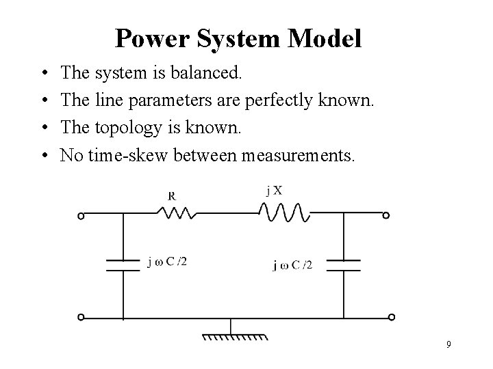
Power System Model • • The system is balanced. The line parameters are perfectly known. The topology is known. No time-skew between measurements. 9
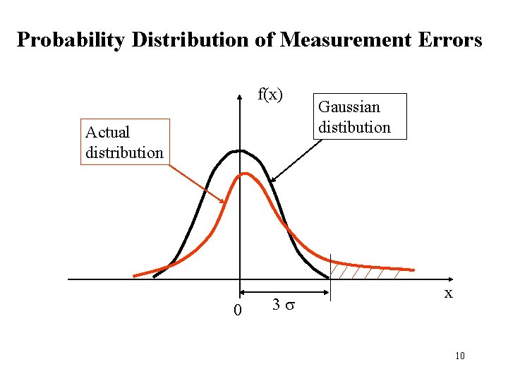
Probability Distribution of Measurement Errors f(x) Actual distribution 0 3 s Gaussian distibution x 10
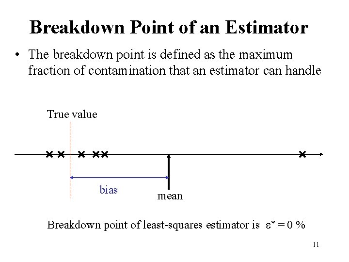
Breakdown Point of an Estimator • The breakdown point is defined as the maximum fraction of contamination that an estimator can handle True value bias mean Breakdown point of least-squares estimator is * = 0 % 11
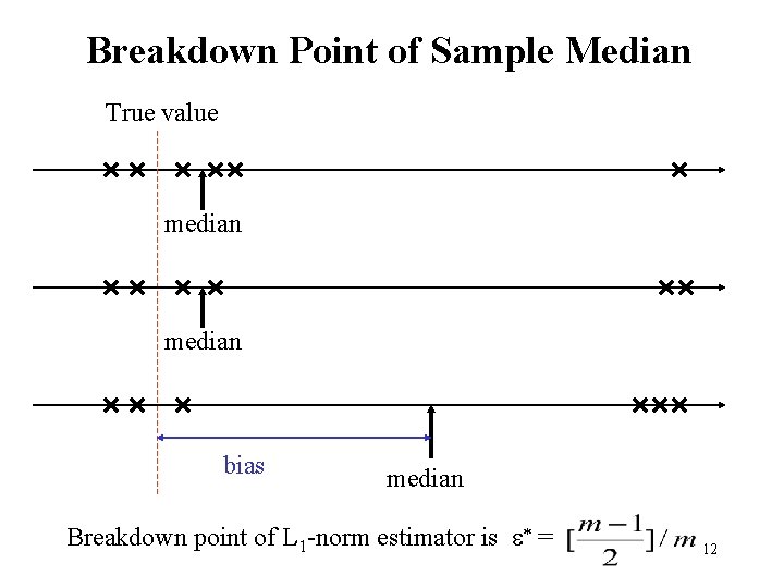
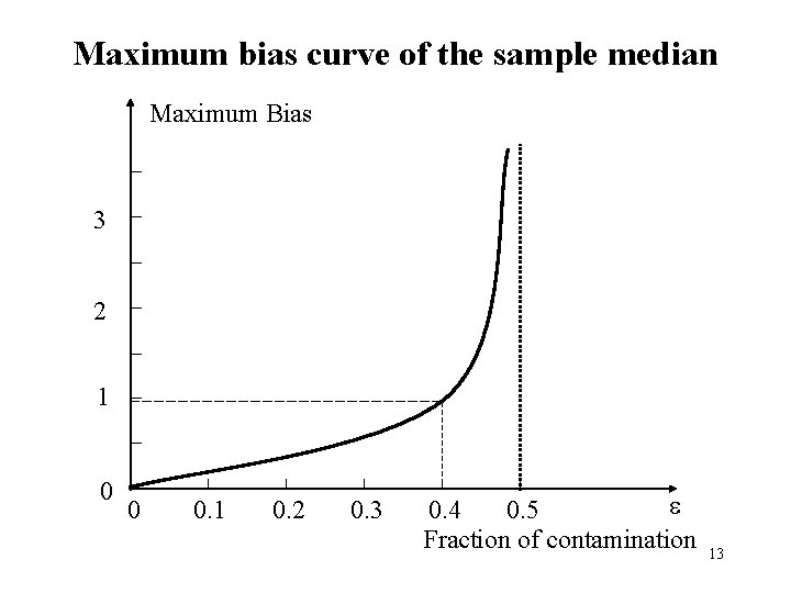
Breakdown Point of Sample Median True value median bias median Breakdown point of L 1 -norm estimator is * = 12
Maximum bias curve of the sample median Maximum Bias 3 2 1 0 0 0. 1 0. 2 0. 3 0. 4 0. 5 Fraction of contamination 13
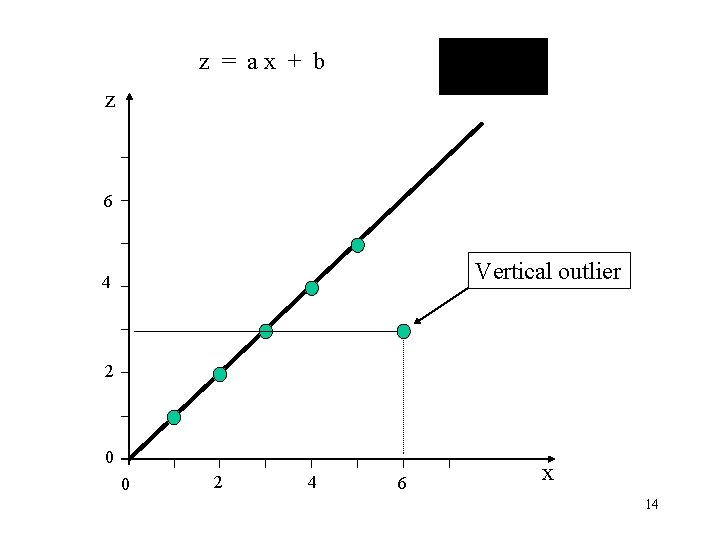
z = ax + b z 6 Vertical outlier 4 2 0 0 2 4 6 x 14
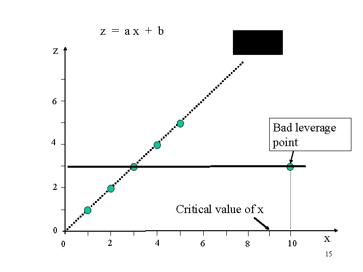
z = ax + b z 6 Bad leverage point 4 2 Critical value of x 0 0 2 4 6 8 10 x 15
Leverage Points in Power Systems • These are distant points (outliers) in the space spanned by the row vectors of the Jacobian matrix. • They are power measurements on relatively short lines. • They are power injection measurements on buses with many incident lines. • Leverage measurements tend also to make the Jacobian matrix ill-conditioned. 16
Leverage Point Processing • Develop robust covariance method for identifying outliers in an n-dimensional point could. • Minimum volume ellipsoid method is a good candidate, but it is computationally intensive. • Projection methods are fast to calculate. • Develop estimation methods that can handle bad leverage points. 17
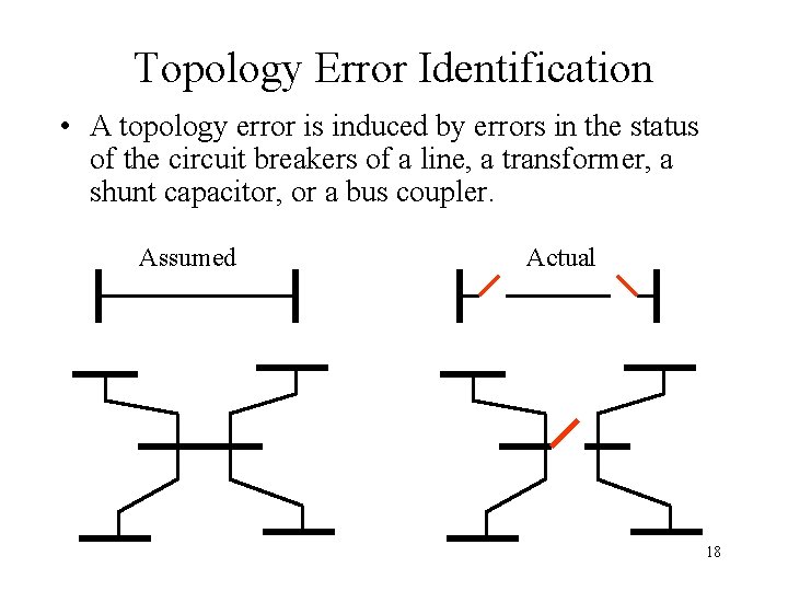
Topology Error Identification • A topology error is induced by errors in the status of the circuit breakers of a line, a transformer, a shunt capacitor, or a bus coupler. Assumed Actual 18
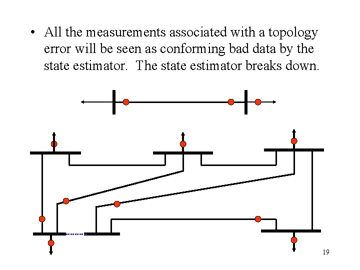
• All the measurements associated with a topology error will be seen as conforming bad data by the state estimator. The state estimator breaks down. 19
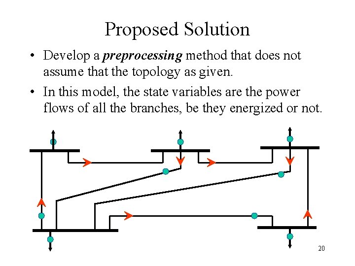
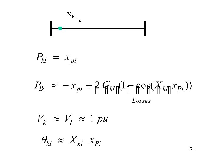
Proposed Solution • Develop a preprocessing method that does not assume that the topology as given. • In this model, the state variables are the power flows of all the branches, be they energized or not. 20
x. Pi 21
Topology estimator • Apply a robust estimation method to estimate the flows through all the branches. • Apply a statistical test to the estimated flows. • If the flow is significantly different from zero, then decide that the associated branch is energized. 22
Parameter estimator • Take advantage of the fact that the state remains nearly unchanged over a certain period of time, typically during the late night off-peak period. • Estimate the nodal voltage magnitudes and phase angles together with the parameters of the lines • Extend the measurement vector by including the metered values recorded at several snapshots. 23
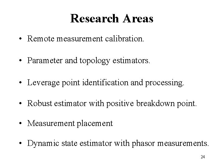
Research Areas • Remote measurement calibration. • Parameter and topology estimators. • Leverage point identification and processing. • Robust estimator with positive breakdown point. • Measurement placement • Dynamic state estimator with phasor measurements. 24