CENTER OF GRAVITY CENTER OF MASS AND CENTROID


- Slides: 25

CENTER OF GRAVITY, CENTER OF MASS AND CENTROID OF A BODY Objective : a) Understand the concepts of center of gravity, center of mass, and centroid. b) Be able to determine the location of these points for a body.

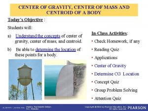
APPLICATIONS To design the structure for supporting a water tank, we will need to know the weights of the tank and water as well as the locations where the resultant forces representing these distributed loads act. How can we determine these weights and their locations?

APPLICATIONS (continued) One concern about a sport utility vehicle (SUV) is that it might tip over while taking a sharp turn. One of the important factors in determining its stability is the SUV’s center of mass. Should it be higher or lower to make a SUV more stable? How do you determine the location of the SUV’s center of mass?

APPLICATIONS (continued) To design the ground support structure for the goal post, it is critical to find total weight of the structure and the center of gravity location. Integration must be used to determine total weight of the goal post due to the curvature of the supporting member. How do you determine the location of its center of gravity?

CONCEPT OF CENTER OF GRAVITY (CG) A body is composed of an infinite number of particles, and so if the body is located within a gravitational field, then each of these particles will have a weight d. W. The center of gravity (CG) is a point, often shown as G, which locates the resultant weight of a system of particles or a solid body. From the definition of a resultant force, the sum of moments due to individual particle weights about any point is the same as the moment due to the resultant weight located at G. Also, note that the sum of moments due to the individual particle’s weights about point G is equal to zero.

CONCEPT OF CG (continued) The location of the center of gravity, measured from the y axis, is determined by equating the moment of W about the y axis to the sum of the moments of the weights of the particles about this same axis. ~ ~~ If d. W is located at point (x, y, z), then _ x W = ~ x d. W _ Similarly, y W = ~ y d. W _ z. W= ~ z d. W Therefore, the location of the center of gravity G with respect to the x, y, z axes becomes

CM & CENTROID OF A BODY By replacing the W with a m in these equations, the coordinates of the center of mass can be found. Similarly, the coordinates of the centroid of volume, area, or length can be obtained by replacing W by V, A, or L, respectively.

CONCEPT OF CENTROID The centroid, C, is a point which defines the geometric center of an object. The centroid coincides with the center of mass or the center of gravity only if the material of the body is homogenous (density or specific weight is constant throughout the body). If an object has an axis of symmetry, then the centroid of object lies on that axis. In some cases, the centroid is not located on the object.

STEPS TO DETERME THE CENTROID OF AN AREA 1. Choose an appropriate differential element d. A at a general point (x, y). Hint: Generally, if y is easily expressed in terms of x (e. g. , y = x 2 + 1), use a vertical rectangular element. If the converse is true, then use a horizontal rectangular element. 2. Express d. A in terms of the differentiating element dx (or dy). 3. Determine coordinates (~x , ~y) of the centroid of the rectangular element in terms of the general point (x, y). 4. Express all the variables and integral limits in the formula using either x or y depending on whether the differential element is in terms of dx or dy, respectively, and integrate. Note: Similar steps are used for determining the CG or CM. These steps will become clearer by doing a few examples.

EXAMPLE Given: The area as shown. Find: The centroid location (x , y) Plan: Follow the steps. Solution 1. Since y is given in terms of x, choose d. A as a vertical rectangular strip. 2. d. A = y dx = x 3 dx ~ ~ 3. x = x and y = y / 2 = x 3 / 2

EXAMPLE(continued) 4. x = ( A ~x d. A ) / ( A d. A ) 1 = 3)dx x (x 0 1/5 [ x 5 ]1 0 = 1 3)dx (x 0 1/4 [ x 4 ]1 0 = ( 1/5) / ( 1/4) = 0. 8 m 1 ~ y = A y d. A A d. A = 3 / 2) ( x 3 ) dx (x 0 0 1 3 x dx = (1/14) / (1/4) = 0. 2857 m = 1/14[x 7]01 1/4

GROUP PROBLEM SOLVING Given: The area as shown. Find: The x of the centroid. Plan: Follow the steps. Solution (x 1, , y) (x 2, y) 1. Choose d. A as a horizontal rectangular strip. 2. d. A = ( x 2 – x 1) dy = ((2 – y) – y 2) dy 3. x = ( x 1 + x 2) / 2 = 0. 5 (( 2 – y) + y 2 )

GROUP PROBLEM SOLVING (continued) 4. ~ = ( A x d. A ) / ( A d. A ) x A d. A = 0 1 ( 2 – y 2) dy [ 2 y – y 2 / 2 – y 3 / 3] 01 = 1. 167 m 2 1 ~ A x d. A = 0 0. 5 ( 2 – y + y 2 ) ( 2 – y 2 ) dy x 1 = 0. 5 0 ( 4 – 4 y + y 2 – y 4 ) dy = 0. 5 [ 4 y – 4 y 2 / 2 + y 3 / 3 – y 5 / 5 ] 1 = 1. 067 m 3 = 0 1. 067 / 1. 167 = 0. 914 m

COMPOSITE BODIES The I-beam or tee-beam shown are commonly used in building various types of structures. When doing a stress or deflection analysis for a beam, the location of the centroid is very important. How can we easily determine the location of the centroid for a given beam shape?

COMPOSITE BODIES (continued) The compressor is assembled with many individual components. In order to design the ground support structures, the reactions at blocks A and B have to be found. To do this easily, it is important to determine the location of the compressor’s center of gravity (CG). If we know the weight and CG of individual components, we need a simple way to determine the location of the CG of the assembled unit.

CG / CM OF A COMPOSITE BODY Consider a composite body which consists of a series of particles(or bodies) as shown in the figure. The net or the resultant weight is given as WR = W. Summing the moments about the y-axis, we get ~ ~ x WR = ~x 1 W 1 + x 2 W 2 + ………. . + xn. Wn ~ where x 1 represents x coordinate of W 1, etc. . Similarly, we can sum moments about the x- and z-axes to find the coordinates of G. By replacing the W with a M in these equations, the coordinates of the center of mass can be found.

CONCEPT OF A COMPOSITE BODY Many industrial objects can be considered as composite bodies made up of a series of connected “simple” shaped parts or holes, like a rectangle, triangle, and semicircle. Knowing the location of the centroid, C, or center of gravity, G, of the simple shaped parts, we can easily determine the location of the C or G for the more complex composite body.

CONCEPT OF A COMPOSITE BODY (continued) This can be done by considering each part as a “particle” and following the procedure as described in Section 9. 1. This is a simple, effective, and practical method of determining the location of the centroid or center of gravity of a complex part, structure or machine.

STEPS FOR ANALYSIS 1. Divide the body into pieces that are known shapes. Holes are considered as pieces with negative weight or size. 2. Make a table with the first column for segment number, the second column for weight, mass, or size (depending on the problem), the next set of columns for the moment arms, and, finally, several columns for recording results of simple intermediate calculations. 3. Fix the coordinate axes, determine the coordinates of the center of gravity of centroid of each piece, and then fill in the table. 4. Sum the columns to get x, y, and z. Use formulas like x = ( xi Ai ) / ( Ai ) or x = ( xi Wi ) / ( Wi ) This approach will become clear by doing examples!

EXAMPLE Given: The part shown. Find: The centroid of the part. Plan: Follow the steps for analysis. Solution: 1. This body can be divided into the following pieces: rectangle (a) + triangle (b) + quarter circular (c) – semicircular area (d). Note the negative sign on the hole!

EXAMPLE (continued) Steps 2 & 3: Make up and fill the table using parts a, b, c, and d. Segment Area A (in 2) x (in) y (in) x A ( in 3) y. A ( in 3) Rectangle Triangle Q. Circle Semi-Circle 18 4. 5 9 /4 – /2 3 7 – 4(3) / (3 ) 0 1. 5 1 4(3) / (3 ) 4(1) / (3 ) 54 31. 5 – 9 0 27 4. 5 9 - 2/3 76. 5 39. 83 28. 0

EXAMPLE (continued) C 4. Now use the table data results and the formulas to find the coordinates of the centroid. Area A 28. 0 x A 76. 5 y. A 39. 83 x = ( x A) / ( A ) = 76. 5 in 3/ 28. 0 in 2 = y = ( y A) / ( A ) = 39. 83 in 3 / 28. 0 in 2 = 2. 73 in 1. 42 in

GROUP PROBLEM SOLVING Given: Two blocks of different materials are assembled as shown. The densities of the materials are: A = 150 lb / ft 3 and B = 400 lb / ft 3. Find: The center of gravity of this assembly. Plan: Follow the steps for analysis. Solution 1. In this problem, the blocks A and B can be considered as two pieces (or segments).

GROUP PROBLEM SOLVING (continued) Weight = w = (Volume in ft 3) w. A = 150 (0. 5) (6) (2) / (12)3 = 3. 125 lb w. B = 400 (6) (2) / (12)3 = 16. 67 lb Segment w (lb) x (in) A B 3. 125 16. 67 19. 79 4 1 y (in) z (in) 1 3 2 3 x. A y. A z. A (lb·in) 12. 5 16. 67 3. 125 50. 00 6. 25 50. 00 29. 17 53. 12 56. 25

GROUP PROBLEM SOLVING (continued) Table Summary W (lb) 19. 79 y w x w zw (lb·in) 29. 17 56. 25 53. 12 Substituting into the equations: ~ x = ( x w) / ( w ) = 29. 17/19. 79 = 1. 47 in y = ( y~ w) / ( w ) = 53. 12/ 19. 79 = 2. 68 in z = ( z~ w) / ( w ) = 56. 25 / 19. 79 = 2. 84 in
 Centroid in engineering mechanics
 Centroid engineering mechanics
 Cg of hemisphere
 Problems on centroid in engineering mechanics
 Gravity for dummies and dummies for gravity equations
 Centroid statics
 What is the inertia of an object
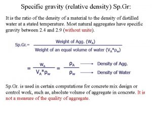
 Units for specific gravity
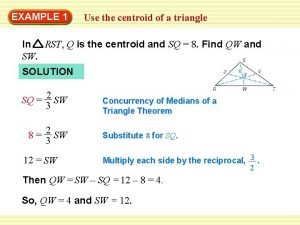
 If m is a centroid of triangle wor and wm = 16, what is wx?
 Relative atomic mass of beryllium
 Atomic
 Isotope abundance formula
 How to write atomic number and mass number
 Centre of gravity in physical education
 Contoh soal metode penentuan lokasi
 Center of gravity method facility location example
 Metode load distance
 Center of gravity method operations management
 Centroid statics
 Gravity in biomechanics
 Centroid subtractive method
 Circumcenter finder
 What is altitude in maths
 Types of facility location
 Centroid of a complex shape
 Centroid exercises
