ANSYS Magnetostatic and Structural Analyses of the s


 W. Meng, 6/17/15 Rout=155. 06 cm")


- Slides: 10
ANSYS Magnetostatic and Structural Analyses of the s. PHENIX Magnet at Full Current John Cozzolino August 17, 2016 1
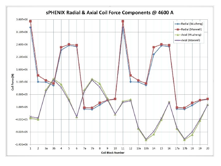
• ANSYS Maxwell Analysis of s. PHENIX Magnet – Final comparison of Maxwell axial and radial coil forces (7/28/16) to Wuzheng Meng’s 2 D results from 6/17/15 • Forces track acceptably (see following chart). • The 2 D Maxwell axisymmetric simulation has functioned properly and generates valid results. 2
Labels on 24 Solenoid Coils (Not to Scale) W. Meng, 6/17/15 Rout=155. 06 cm Rin=150. 98 cm Coil-package ctr. 3. 0 cm (solenoids/yoke/poles common Axis) Z Z=0 (Yoke axial ctr. ) 4
• ANSYS Maxwell Analysis of s. PHENIX Magnet – 3 D magnetostatic FE analysis of the coil in the iron • Geometry is taken from the simplified Creo solid model. – The coil center is shifted 3 cm north relative to the iron. » The iron weight is approximately 1, 320, 000 lb. » The fringe B field outside the iron is observed at 4600 A. » The simplified 3 D FE model is used to compare end forces on the iron to Wuzheng’s calculations from 6/17/2015. 5
• Static B field vector plot at 4600 A • Scale is 0 to ≥ 4. 3 Gauss (red) • Axial limit of region is about 8 m from magnet center. • The blue region does not exceed 1. 7 Gauss.
• Axial Forces on s. PHENIX Iron End Caps at 4600 A with 3 & 4 cm Coil Offsets North South Iron North Iron 7
• ANSYS Maxwell Analysis of s. PHENIX Magnet – 3 D magnetostatic and static structural FE analysis of the iron at 4600 A • Geometry is taken from the latest Creo solid model. – One side wall includes actual physical features and realistic contact conditions. » Therefore, deflections should better represent actual behavior. 8
• ANSYS Maxwell Analysis of s. PHENIX Magnet • One side wall is modeled in detail. • Frictionless contact is applied where appropriate. • Bolts are in place but are not preloaded in the model. • Max inward deflection is. 011 inch (blue). • Note: This model lacks some of the latest features such as heavy angle braces and additional fasteners. • The effect of such iron deflections on the cryostat via its support struts has not yet been studied. 9
• ANSYS Maxwell Analysis of s. PHENIX Magnet • Structural FE analysis of the cryostat support system is the logical next step. • The yoke assembly should include all newly added relevant features including steel gussets, additional bracing, and doublers. • Effects of the 30, 000 lbf axial load imbalance should be considered as well. • Consider verifying the axial location of the solenoid relative to the iron. 10