Wheel and Axle Lever MACHINES Pulley Screw Inclined


 •")


- Slides: 36
Wheel and Axle Lever MACHINES Pulley Screw Inclined Plane Wedge
SIMPLE MACHINES WHY? • Simple machines are useful because they can make a physical job easier by changing the magnitude or the direction of the force exerted to do work.
Have you ever tried to unscrew a nut, bolt, or screw from something with your bare hands and discovered that it was just too tight to loosen even if you had a good grip?
You got the proper tool, such as a screw driver or wrench, and unscrewed it!
Why is it that it is so easy to unscrew with a tool when you can't with your bare hands?
The wrench and screw driver are examples of a wheel and axle, where the screw or bolt is the axle and the handle is the wheel. The tool makes the job easier by changing the amount of the force you exert. Wheel Axle
All of the simple machines can be used for thousands of jobs from lifting a 500 -pound weight to making a boat go. The reason why these machines are so special is because they make difficult tasks much easier.
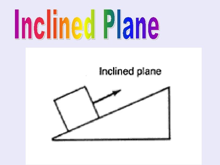
• A sloping surface, like a ramp, that reduces the amount of force needed to lift something by increasing the distance over which the force is applied. • In other words, it reduces the amount of force needed.
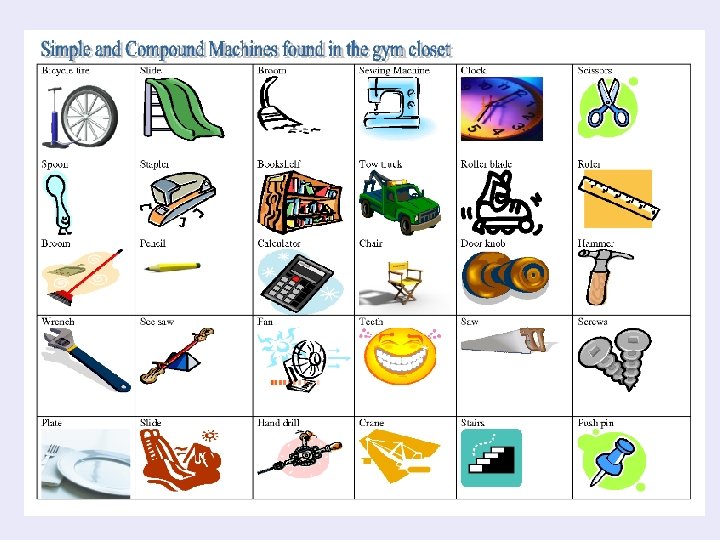
EXAMPLES
MECHANICAL ADVANTAGE THE INCLINED PLANE – Reduces the amount of force by: – Increasing the distance over which the force is applied. – As the ramp is made longer and less steep, less force is required.
• An inclined plane wrapped in a spiral around a cylindrical post. • As you turn the screw, the threads pull the screw into the wood. • The inclined plane slides through the wood.
EXAMPLES
• An inclined plane with one or two sloping sides. • Two inclined planes make a wedge. • Wedges change the direction of the force.
EXAMPLES
• A bar that is free to pivot or turn around a fixed point. Lever Load Fulcrum – fixed point
LEVERS
LEVERS There are three classes of levers and each is based on the position of the fulcrum.
st 1 CLass Examples: Crowbars, pliers, scissors, seesaw The fulcrum is between the resistance force and the effort force. The closer the fulcrum to the resistance force, the more the lever multiplies the force.
nd 2 Class • Wheelbarrow • Nutcrackers • Crowbar (forcing two objects apart) • The handle of a pair of nail clippers 2 nd Class: The resistance force is between the effort force and the fulcrum.
rd 3 Class 3 rd Class: the effort force is between the resistance force and the fulcrum. • Garden Hoe • Your arm • Catapult • Fishing rod • Tongs (double lever) (where hinged at one end)
CLASSES OF LEVERS First Class Fulcrum is between Fe and Fr Second Class Fr is between the Fe and fulcrum Third Class Fe is between the Fr and the fulcrum
MECHANICAL ADVANTAGE LEVER – Makes work easier by: – Multiplying your effort force and changing the direction of your force
LEVERS
A grooved wheel with a rope, chain, or cable running along the grove. Wheel Rope The two sides of the pulley are the effort arm and the resistance arm.
FIXED PULLEY • A modified first class lever; the axle of the pulley acts as the fulcrum. • Cannot multiply the effort force, ONLY changes the direction of the effort force.
MOVEABLE PULLEY • One end of the rope is fixed and the pulley or wheel is free to move • Can multiply the effort force and change the direction of the effort force. • Because effort force increases, the distance must increase to conserve energy. You pull more. Pulleys
EXAMPLES
A machine consisting of two wheels of different sizes that rotate together. Wheel Axle
WHEEL AND AXLE • Usually the effort is exerted on the larger wheel. Then the smaller wheel (axle) exerts the resistance force. • A modified lever.
EXAMPLES
MECHANICAL ADVANTAGE WHEEL AND AXLE – The effort arm is the radius of the wheel – The resistance arm is the radius of the axle – The mechanical advantage of a wheel and axle can be increased by making the radius of the wheel larger.
COMPOUND MACHINES • When two or more simple machines are used together. • The overall MA of the compound machine is related to the MA of all the machines involved.
EXAMPLES