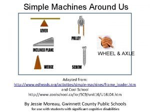
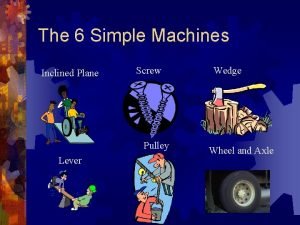
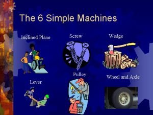
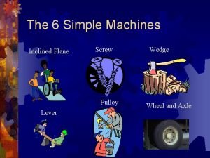
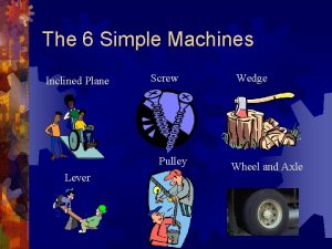
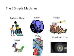
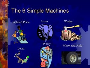
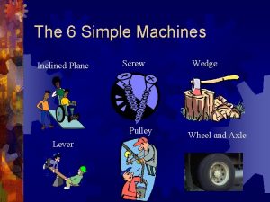
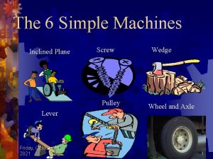
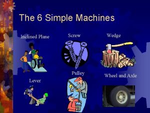
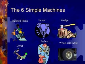
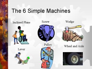
The 6 Simple Machines Inclined Plane Screw Pulley


- Slides: 18

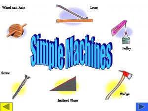
The 6 Simple Machines Inclined Plane Screw Pulley Lever Wedge Wheel and Axle

Inclined Plane

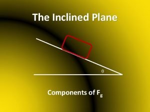
Inclined Planes ® An inclined plane is a flat surface that is higher on one end ® An inclined plane doesn’t move. ® Inclined planes make the work of moving things easier

Screw

Screw

Wedges ® Two inclined planes joined back to back. ® Wedges are used to split things. ® Wedges move where inclined planes don’t.

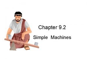
A lever uses force to move something

First Class Lever Fulcrum is between EF (effort) and RF (load)

First Class Lever. ® Common examples of first-class levers include crowbars, scissors, pliers, tin snips and seesaws.

Second Class Lever RF (load) is between fulcrum and EF

Second Class Lever ® Examples of second-class levers include nut crackers, wheel barrows, doors, and bottle openers.

Third Class Lever EF is between fulcrum and RF (load)

Third Class Lever ® Examples of third-class levers include tweezers, arm hammers, and shovels.

Pulleys ® Pulley are wheels and axles with a groove around the outside ® A pulley needs a rope, chain or belt around the groove to make it do work

Diagrams of Pulleys Fixed pulley: Movable Pulley: A fixed pulley changes the direction of a force; however, it does not create a mechanical advantage. The mechanical advantage of a moveable pulley is equal to the number of ropes that support the moveable pulley.

COMBINED PULLEY ® The effort needed to lift the load is less than half the weight of the load. ® The main disadvantage is it travels a very long distance.

WHEEL AND AXLE ® The axle is stuck rigidly to a large wheel. Fan blades are attached to the wheel. When the axel turns, the fan blades spin.

GEARS-Wheel and Axle ® Each gear in a series reverses the direction of rotation of the previous gear. The smaller gear will always turn faster than the larger gear.
 Quiz 4: inclined plane, wedge, and screw
 Wedge and inclined plane
 Ama of a wedge
 Blinds simple machine
 Simple machines examples
 6 simple machines examples
 Screw simple machines
 What is pulleys
 A flat belt connects pulley a to pulley b
 A flat belt connects pulley a to pulley b
 Uses of wheel and axle
 Data plane control plane and management plane
 Different types of inclined planes
 Examples of inclined plane
 Curved inclined plane
 Simple machines history
 Levers and inclined planes
 Good morning in mandarin
 Blank is an inclined plane wrapped in a cylindrical post
