Vacuum cryo links Design issues Jo van den

- Slides: 11
Vacuum / cryo links Design issues Jo van den Brand, Martin Doets Nikhef jo@nikhef. nl martind@nikhef. nl Cascina Feb. 3, 2009
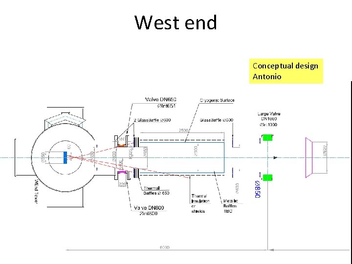
West end Conceptual design Antonio
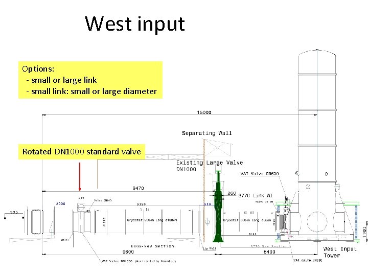
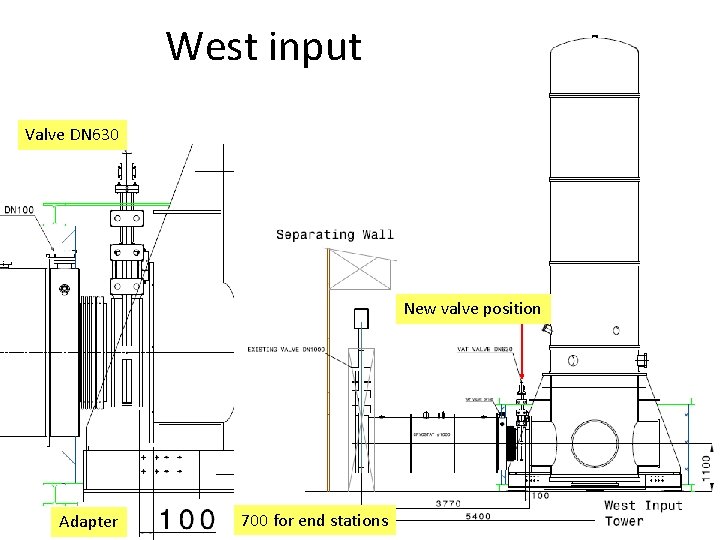
West input Options: - small or large link - small link: small or large diameter Rotated DN 1000 standard valve
West input Valve DN 630 New valve position Adapter 700 for end stations
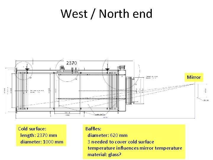
West / North end 2370 Mi Mirror Cold surface: length: 2370 mm diameter: 1000 mm Mi Baffles: diameter: 620 mm 3 needed to cover cold surface temperature influences mirror temperature material: glass?
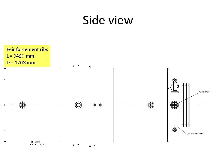
Side view Reinforcement ribs L = 3490 mm D = 1208 mm
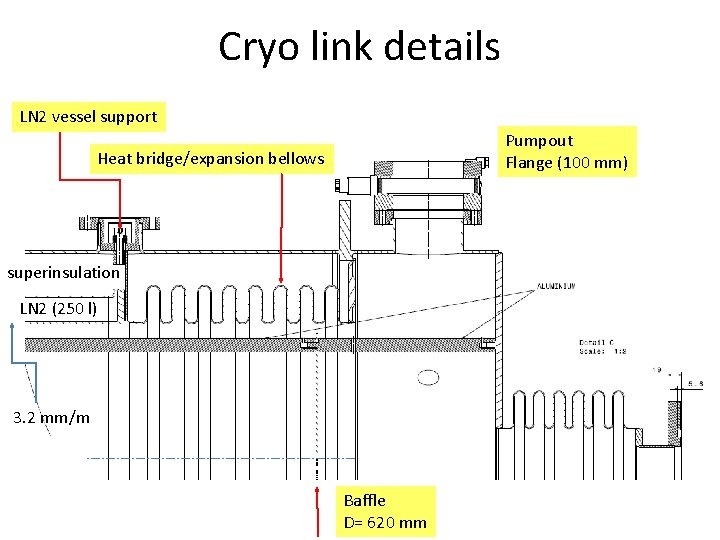
Cryo link details LN 2 vessel support Pumpout Flange (100 mm) Heat bridge/expansion bellows superinsulation LN 2 (250 l) 3. 2 mm/m Baffle D= 620 mm
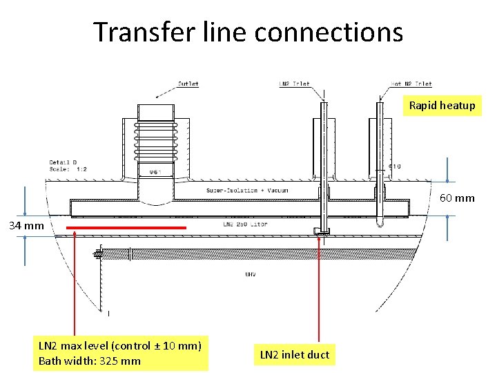
Transfer line connections Rapid heatup 60 mm 34 mm LN 2 max level (control ± 10 mm) Bath width: 325 mm LN 2 inlet duct
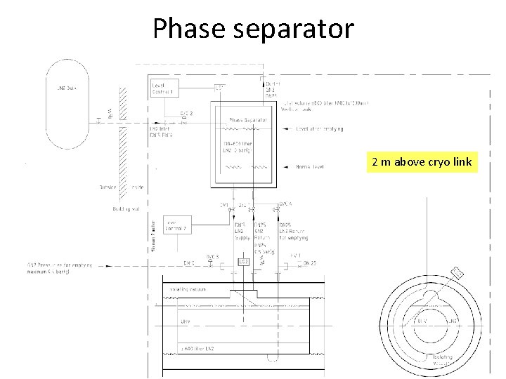
Phase separator 2 m above cryo link
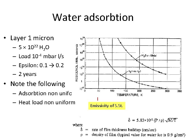
Water adsorbtion • Layer 1 micron – – 5 × 10²² H 2 O Load 10 -4 mbar l/s Epsilon: 0. 1 → 0. 2 2 years • Note the following – Adsorbtion non uniform – Heat load non uniform Emissivity of S. St.
Summary • Preliminary design for short cryo links – Length 2. 5 m, diameter 1 m – Capacity about 2 years for 1 micron layer – Reduced heat load • Lower gas load, less bubbles, less nois • Lower LN 2 consumption – Effect on mirrors – Reduced cost • Test set-up – Operations • Closed loop condensor – Bubbles – Etc.