Topic 11 11 4 Diffraction Diffraction Single edge


- Slides: 20
Topic 11 11. 4 Diffraction
Diffraction
Single edge § This is the diffraction pattern produced around the edge of a razor blade
Narrow Slit
Circular Aperture § The diffraction fringe pattern produced by a circular aperture.
Diffraction Patterns § When plane wavefronts pass through a small aperture they spread out § This is an example of the phenomenon called diffraction § Light waves are no exception to this
§ However, when we look at the diffraction pattern produced by light we observe a fringe pattern, § that is, on the screen there is a bright central maximum with "secondary" maxima either side of it. § There also regions where there is no illumination and these minima separate the maxima.
§ This intensity pattern arises from the fact that each point on the slit acts, in accordance with Huygen's principle, as a source of secondary wavefronts. § It is the interference between these secondary wavefronts that produces the typical diffraction pattern.
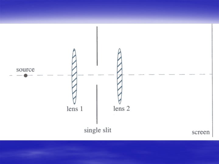
Derivation of Equation § We can deduce a useful relationship from a simple argument. § In this argument we deal with something that is called Fraunhofer diffraction, § that is the light source and the screen are an infinite distance away form the slit. § This can be achieved with the set up shown in the next figure.
§ The source is placed at the principal focus of lens 1 and the screen is placed at the principal focus of lens 2. § Lens 1 ensures that parallel wavefronts fall on the single slit and lens 2 ensures that the parallel rays are brought to a focus on the screen. § The same effect can be achieved using a laser and placing the screen some distance from the slit.
§ To obtain a good idea of how the single slit pattern comes about we consider the next diagram
§ In particular we consider the light from one edge of the slit to the point P where this point is just one wavelength further from the lower edge of the slit than it is from the upper edge. § The secondary wavefront from the upper edge will travel a distance λ/2 further than a secondary wavefront from a point at the centre of the slit. § Hence when these wavefronts arrive at P they will be out of phase and will interfere destructively.
§ The wavefronts from the next point below the upper edge will similarly interfere destructively with the wavefront from the next point below the centre of the slit. § In this way we can pair the sources across the whole width of the slit.
§ If the screen is a long way from the slit then the angles θ 1 and θ 2 become nearly equal. § From the previous figure we see therefore that there will be a minimum at P if § λ = b sin θ 1 § where b is the width of the slit.
§ However, both angles are very small, equal to θ say, so we can write that § θ =λ/b § This actually gives us the half-angular width of the central maximum. § We can calculate the actual width of the maximum along the screen if we know the focal length of the lens focussing the light onto the screen. If this is f then we have that § θ =d/f § Such that § d=fλ/b
§ To obtain the position of the next maximum in the pattern we note that the path difference is 3/2 λ. § We therefore divide the slit into three equal parts, two of which will § produce wavefronts that will cancel and the other producing wavefronts that reinforce. The intensity of the second maximum is therefore much less than the intensity of the central maximum. § (Much less than one third in fact since the wavefronts that reinforce will have differing phases).
Example § Light from a laser is used to form a single slit diffraction pattern. The width of the slit is 0. 10 mm and the screen is placed 3. 0 m from the slit. The width of the central maximum is measured as 2. 6 cm. What is the wavelength of the laser light?
Answer § Since the screen is a long way from the slit we can use the small angle approximation such that the f in d = f λ / b becomes 3. 0 m. (i. e. f is the distance from the slit to the screen) § The half width of the centre maximum is 1. 3 cm so we have § λ = (1. 3 x 10 -2) x(0. 10 x 10 -3) / 3. 0 § λ = 430 x 10 -9 or 430 nm