
TMD Thermal Mapping Drone Jamyang Tenzin Dylan Fallon
- Slides: 2
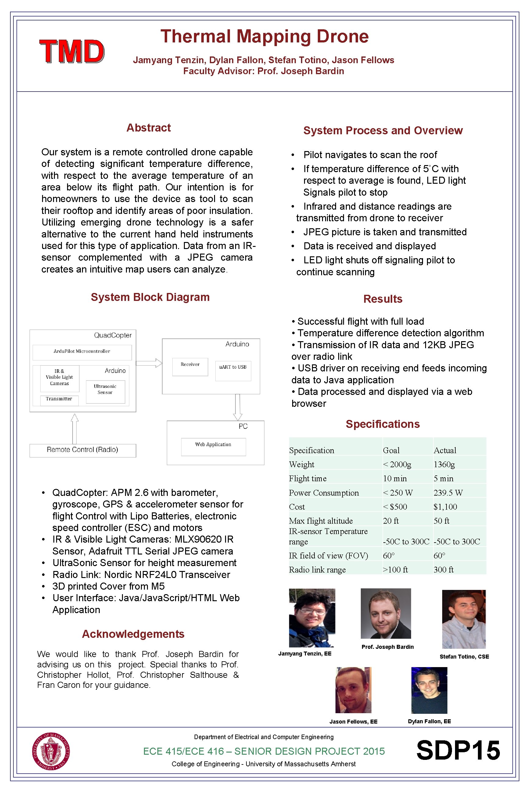
TMD Thermal Mapping Drone Jamyang Tenzin, Dylan Fallon, Stefan Totino, Jason Fellows Faculty Advisor: Prof. Joseph Bardin Abstract System Process and Overview Our system is a remote controlled drone capable of detecting significant temperature difference, with respect to the average temperature of an area below its flight path. Our intention is for homeowners to use the device as tool to scan their rooftop and identify areas of poor insulation. Utilizing emerging drone technology is a safer alternative to the current hand held instruments used for this type of application. Data from an IRsensor complemented with a JPEG camera creates an intuitive map users can analyze. • Pilot navigates to scan the roof • If temperature difference of 5˚C with respect to average is found, LED light Signals pilot to stop • Infrared and distance readings are transmitted from drone to receiver • JPEG picture is taken and transmitted • Data is received and displayed • LED light shuts off signaling pilot to continue scanning System Block Diagram Results • Successful flight with full load • Temperature difference detection algorithm • Transmission of IR data and 12 KB JPEG over radio link • USB driver on receiving end feeds incoming data to Java application • Data processed and displayed via a web browser Specifications • Quad. Copter: APM 2. 6 with barometer, gyroscope, GPS & accelerometer sensor flight Control with Lipo Batteries, electronic speed controller (ESC) and motors • IR & Visible Light Cameras: MLX 90620 IR Sensor, Adafruit TTL Serial JPEG camera • Ultra. Sonic Sensor for height measurement • Radio Link: Nordic NRF 24 L 0 Transceiver • 3 D printed Cover from M 5 • User Interface: Java/Java. Script/HTML Web Application Specification Goal Actual Weight < 2000 g 1360 g Flight time 10 min 5 min Power Consumption < 250 W 239. 5 W Cost < $500 $1, 100 Max flight altitude IR-sensor Temperature range 20 ft 50 ft IR field of view (FOV) 60° Radio link range >100 ft 300 ft -50 C to 300 C Acknowledgements We would like to thank Prof. Joseph Bardin for advising us on this project. Special thanks to Prof. Christopher Hollot, Prof. Christopher Salthouse & Fran Caron for your guidance. Prof. Joseph Bardin Jamyang Tenzin, EE Jason Fellows, EE Department of Electrical and Computer Engineering ECE 415/ECE 416 – SENIOR DESIGN PROJECT 2015 College of Engineering - University of Massachusetts Amherst Stefan Totino, CSE Dylan Fallon, EE SDP 15
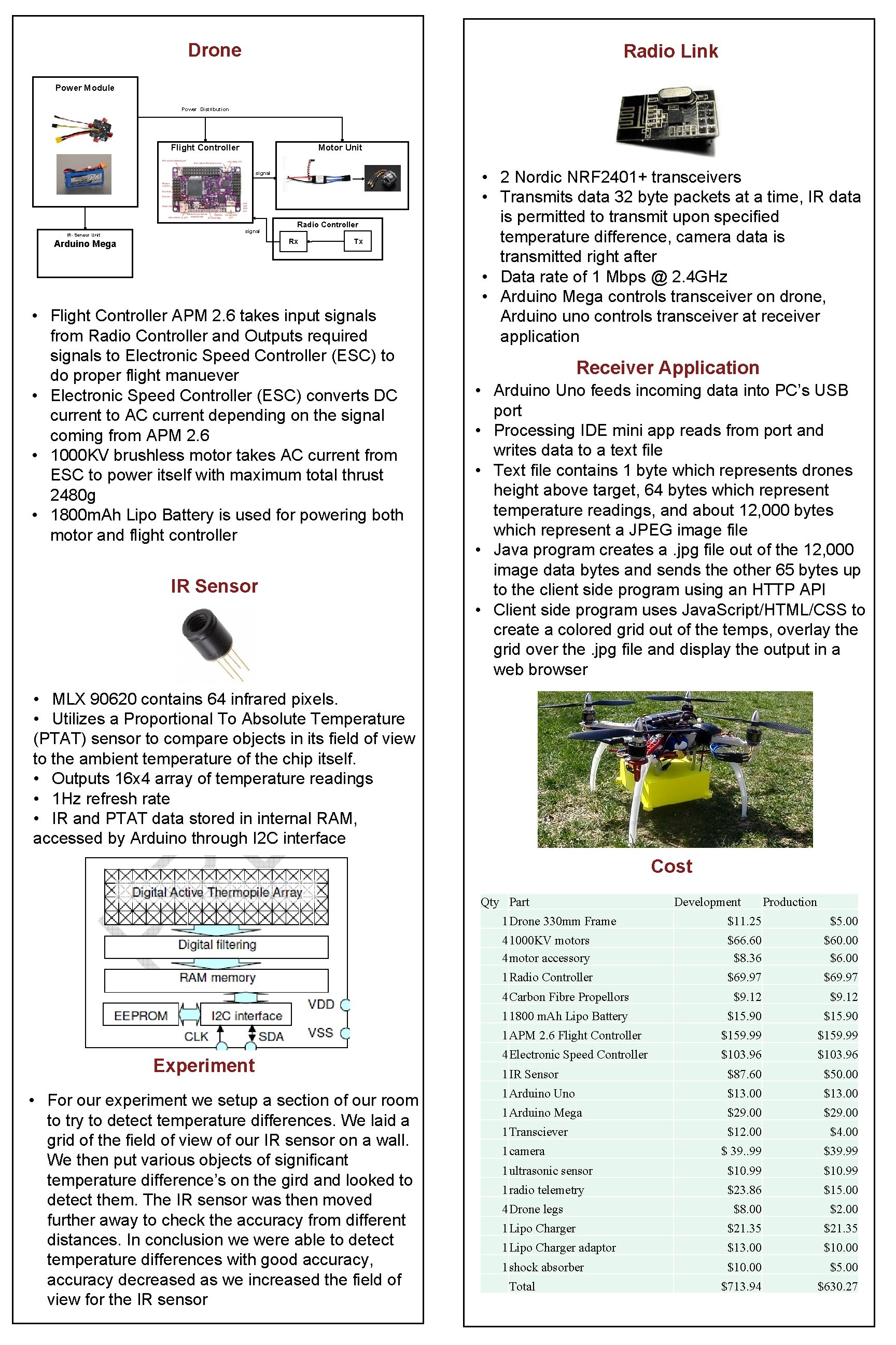
Drone Radio Link Power Module Power Distribution Flight Controller Motor Unit signal IR- Sensor Unit signal Radio Controller Rx Arduino Mega Tx • Flight Controller APM 2. 6 takes input signals from Radio Controller and Outputs required signals to Electronic Speed Controller (ESC) to do proper flight manuever • Electronic Speed Controller (ESC) converts DC current to AC current depending on the signal coming from APM 2. 6 • 1000 KV brushless motor takes AC current from ESC to power itself with maximum total thrust 2480 g • 1800 m. Ah Lipo Battery is used for powering both motor and flight controller IR Sensor • 2 Nordic NRF 2401+ transceivers • Transmits data 32 byte packets at a time, IR data is permitted to transmit upon specified temperature difference, camera data is transmitted right after • Data rate of 1 Mbps @ 2. 4 GHz • Arduino Mega controls transceiver on drone, Arduino uno controls transceiver at receiver application Receiver Application • Arduino Uno feeds incoming data into PC’s USB port • Processing IDE mini app reads from port and writes data to a text file • Text file contains 1 byte which represents drones height above target, 64 bytes which represent temperature readings, and about 12, 000 bytes which represent a JPEG image file • Java program creates a. jpg file out of the 12, 000 image data bytes and sends the other 65 bytes up to the client side program using an HTTP API • Client side program uses Java. Script/HTML/CSS to create a colored grid out of the temps, overlay the grid over the. jpg file and display the output in a web browser • MLX 90620 contains 64 infrared pixels. • Utilizes a Proportional To Absolute Temperature (PTAT) sensor to compare objects in its field of view to the ambient temperature of the chip itself. • Outputs 16 x 4 array of temperature readings • 1 Hz refresh rate • IR and PTAT data stored in internal RAM, accessed by Arduino through I 2 C interface Cost Qty Part Experiment • For our experiment we setup a section of our room to try to detect temperature differences. We laid a grid of the field of view of our IR sensor on a wall. We then put various objects of significant temperature difference’s on the gird and looked to detect them. The IR sensor was then moved further away to check the accuracy from different distances. In conclusion we were able to detect temperature differences with good accuracy, accuracy decreased as we increased the field of view for the IR sensor Production 1 Drone 330 mm Frame $11. 25 $5. 00 41000 KV motors 4 motor accessory $66. 60 $8. 36 $60. 00 $6. 00 1 Radio Controller $69. 97 4 Carbon Fibre Propellors $9. 12 11800 m. Ah Lipo Battery $15. 90 1 APM 2. 6 Flight Controller $159. 99 4 Electronic Speed Controller $103. 96 1 IR Sensor $87. 60 $50. 00 1 Arduino Uno $13. 00 1 Arduino Mega $29. 00 1 Transciever $12. 00 $4. 00 1 camera $ 39. . 99 $39. 99 1 ultrasonic sensor $10. 99 1 radio telemetry $23. 86 $15. 00 $8. 00 $2. 00 1 Lipo Charger $21. 35 1 Lipo Charger adaptor $13. 00 $10. 00 1 shock absorber $10. 00 $5. 00 $713. 94 $630. 27 4 Drone legs Development Total


