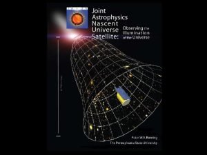
The Mission The Mission Explore the Dark Ages


- Slides: 16

The Mission § § § The Mission Explore the Dark Ages through the neutral hydrogen distribution Constrain the populations of the first stars and first black holes. Measure density fluctuations in the early universe Obtain the equation of state of dark energy test alternate theories of gravity [The first 4 slides are taken from Greg Taylor’s presentation on telescope requirements to LARC/DALI meeting at GSFC in Jan 2009]

Assumptions § § Assumptions Array to be located on the Far Side of the Moon § § § Observe during the Lunar night (50% duty cycle) § § § Minimizes terrestrial RFI Minimizes Ionospheric Fluctuations Minimizes solar RFI Array to consist of N stations, each with M dipole pairs Each station will be capable forming B beams on the sky Array assumed to be deployed in a locally flat region Array is to be deployed robotically 2

Scientific Requirements § Scientific § § § § requirements Redshift range: z=50 to 6 Angular resolution: 1. 4’ Bandwidth: 8 MHz Sensitivity in 1000 h at z=15: 0. 2 micro. Jy/beam Brightness Sensitivity: 4 milli. K FOV: 11 sq deg Dual Circular Dynamic range: 106 to 107 3

Technical Requirements § Technical § § § Frequency range: 30 - 200 MHz Collecting area: 3. 0 km 2 Maximum baseline: 10 km Bandwidth: 8 MHz Station Diameter: 150 m § § requirements Number of Stations: 300 Number of Beams: 9 Dipole pairs in each station: 1500 Antenna FOV: 45 deg FWHM 4

Ground-based reionization experiments

Science Goals of the Murchison Widefield Array • Epoch of Reionization • Heliospheric Physics • Astronomical transients Sited in Western Australia MIT Haystack Observatory MIT Kavli Institute Harvard-Smithsonian Center for Astrophysics Australia National University Melbourne University + consortium Raman Research Institute Chippendale & Beresford 2007

Antenna tile 32 antenna tiles Imaging by R. Wayth 26 -tile MWA image Simulation

Current Phase is MWA “Demonstrator” (under construction) N=512; D=4 m - LARGE etendue; good foreground subtraction Digitized at antenna (660 Msamples/sec) - direct conversion Raw data rate = 512 X 660 MHz X 10 bits = 844 GB/sec After digital filters and correlator: 20 GB/sec (32 MHz bandwidth; 2 Gvis per half-second) Real-time antenna and ionosphere calibration every 8 seconds Map of antenna tile field of view (~30 degrees across) every 8 seconds Status: 32 tiles on site; currently taking data with 26 tiles

MWA power spectrum sensitivity (in principle) at redshift 8 Reionization spatial power spectrum Bowman, Morales & Hewitt (2006)

C. Carilli, A. Datta (NRAO/SOC), J. Aguirre, D. Jacobs (U. Penn) • Focus: Reionization (power spec, CSS, abs) • Very wide field: 30 deg

PAPER: Staged Engineering • Broad band sleeve dipole + flaps • FPGA-based ‘pocket correlator’ from Berkeley wireless lab, routing via switch • S/W Imaging, calibration, PS analysis: AIPY, including ionospheric ‘peeling’ calibration, W projection… 100 MHz 200 MHz BEE 2: 5 FPGAs, 500 Gops/s

150 MHz PWA-4/PGB-8 Powerspectrum

Antenna Development for LUNAR (Bradley NRAO) Optimize the electromagnetic behavior of the four-element helical array through parametric modeling. Study effects of lunar deployment tolerances. Develop a viable mechanical design for the lowmass, folding antenna truss structure. Build prototypes for operation at 137 MHz and determine beam patterns by measuring the downlink power from a constellation of LEO satellites.

LARC Concept of the Lunar Radio Array Notional design completed as part of NASA Award NNX 08 AM 30 G

The Self-Tending Array Node and Communications Element -- STANCE -- Quad helical antennas, grounding cavity, and folding support truss adopted as the baseline design.

NRAO Statement of Work: Software requirements Years 3 + 4: half-time postdoc position will be used to study the software requirements for the lunar array to detection the cosmological HI 21 cm singal. Funding for the other-half time is being sought within the NRAO algorithms development group. Goals: 1. Report on telescope software requirement, based on science requirements and design, summarizing processing and analysis software requirements. 2. A report reviewing the current software being written for low frequency ground-based arrays, making recommendations as to aspects of these systems that can be incorporated into the Lunar software design. 3. If time allows, explore low frequency data processing using data from existing low frequency instruments.
 Renaissance vs medieval art
 Dark ages vs middle ages
 Dark ages vs renaissance
 Dark ages video questions
 Medieval period mosaic
 Physical education during feudalism
 Greek dark ages timeline
 Dark ages def
 Grabalaptop
 Middle ages renaissance
 Feudal system definition
 In the dark dark town
 Dark matter and dark energy presentation
 Explore the alternatives in decision making
 Www.careeronestop.org/explore careers
 Fungsi manajemen explore
 Thinglink 360 images

