SWEN 5130 REQUIREMENTS ENGINEERING Unified Modeling Language Short


- Slides: 17
SWEN 5130 REQUIREMENTS ENGINEERING Unified Modeling Language Short Tutorial By Yuvaraj Mani Teaching Assistant SWEN 5130 Spring semester 2006
UML • UML stands for Unified Modeling Language • Used for preparing Software Blue Prints • Applicable to any domain ranging from enterprise information-systems to distributed Web-based applications • UML is process independent • UML is language and platform independent
UML LANGUAGE FOR • VISUALIZING: Graphical models representing the system to be developed • SPECIFYING: Models are Precise, clear and complete to capture all the requirements • CONSTRUCTING: with the help of precise, unambiguous graphical model it is easy for the programmer to develop the code UML permits forward and reverse engineering • DOCUMENTING: The diagrams developed provides vital information sharing and communicating the knowledge about the system
PRIMARY INFLUENCES on the UML • BOOCH - parameterized classes, visibility • EMBLEY - singleton classes, high-level views • FUSION - operation descriptions, object interaction graphs • HAREL - state charts • JACOBSON - use cases • JHONSON - frameworks • MEYER - preconditions and post conditions • ODELL - dynamic and multiple classifications
Using Rational Rose on Windows platform Click on Start All Programs Rational software Rational Rose Enterprise Edition
Using Rational Rose in Windows Platform
USE CASES • A Use Case is a description of a set of sequences of actions, including variants, that a system performs to yield an observable result of value to an end-user • Use cases specifies and captures the intended behavior of the system. • It is the main communication tool with end –user • A Use case specifies what a system or a subsystem, class, or interface does • It does not specify how the system does it • Identifying the Use cases is very important in capturing the requirements. • Graphically, a Use Case is rendered as an ellipse.
ACTORS • Actors are users of the system • An Actor represents a role that a human, a hardware device, or even another system plays with a system. • Actors interact with the system through use cases • In the use case diagram actors are connected through arrows to the use cases • Graphically, an actor is rendered like this
IDENTIFYING USE CASES • Use case names are short verb phrases representing some behavior of the system. • First identify Actors involved in the system • Actors are the ones who is going to be using the system directly. • List all the actors and determine each ways in which the actor interacts with the system • Identify the verb phrases of the system, these phrases will be the use cases
USE CASES EXAMPLES
ACTORS EXAMPLES
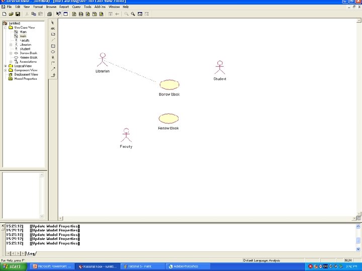
USE CASE DIAGRAM EXAMPLE Library Management Systems
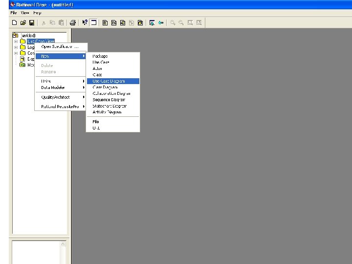
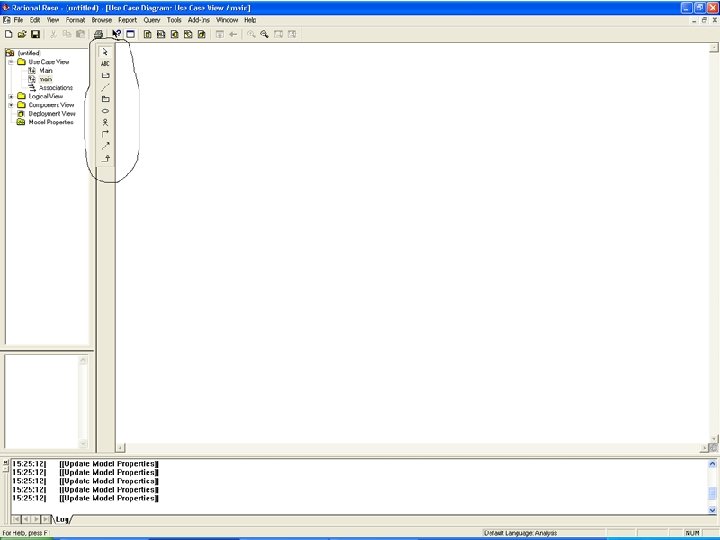
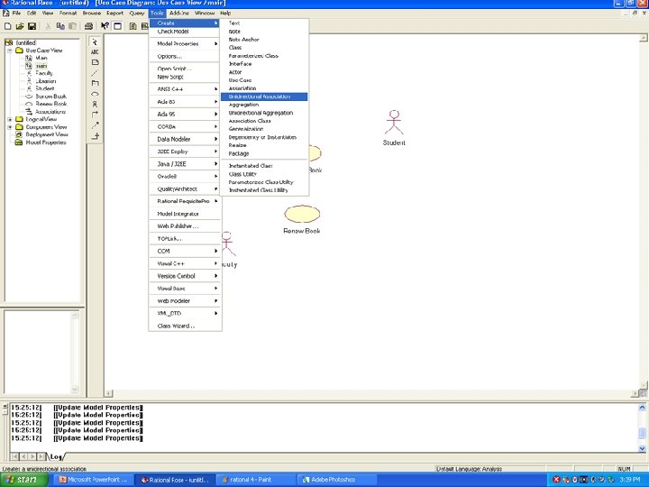
DRAWING USE CASE DIAGRAM IN RATIONAL ROSE • On the Left hand side of the Window on the folder Use Case view Right click New Use case Diagram • Give a name to the Use Case diagram and double click on it to get the whit space on to the Right. • On the middle there are Graphical icons of Actors and Use cases click on the Icons you need and Drag them and Drop them in the White Drawing Area on the Right Hand side of the Screen • Double click the Actors and Use cases on the Drawing space to Name them. • For creating Associations between Actors and Use cases go to Tools Create Association • Then with the cursor we can associate Use cases and Actors.