SURVEYING I CE 128 TESTING A CHAIN When
- Slides: 20
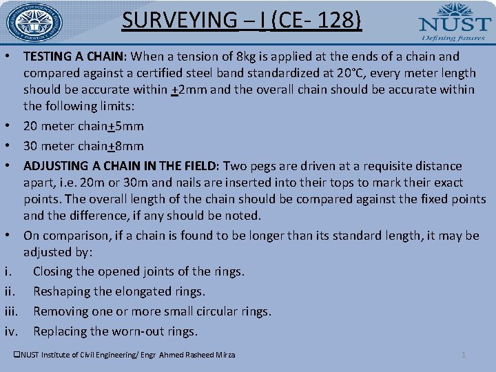
SURVEYING – I (CE- 128) • TESTING A CHAIN: When a tension of 8 kg is applied at the ends of a chain and compared against a certified steel band standardized at 20°C, every meter length should be accurate within +2 mm and the overall chain should be accurate within the following limits: • 20 meter chain+5 mm • 30 meter chain+8 mm • ADJUSTING A CHAIN IN THE FIELD: Two pegs are driven at a requisite distance apart, i. e. 20 m or 30 m and nails are inserted into their tops to mark their exact points. The overall length of the chain should be compared against the fixed points and the difference, if any should be noted. • On comparison, if a chain is found to be longer than its standard length, it may be adjusted by: i. Closing the opened joints of the rings. ii. Reshaping the elongated rings. iii. Removing one or more small circular rings. iv. Replacing the worn-out rings. q. NUST Institute of Civil Engineering/ Engr Ahmed Rasheed Mirza 1
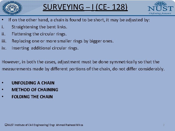
SURVEYING – I (CE- 128) • If on the other hand, a chain is found to be short, it may be adjusted by: i. Straightening the bent links. ii. Flattening the circular rings. iii. Replacing one or more smaller rings by bigger ones. iv. Inserting additional circular rings. However, in both the cases, adjustment must be done symmetrically so that the measurements made by different portions of the chain, do not differ considerably. • • • UNFOLDING A CHAIN METHOD OF CHAINING FOLDING THE CHAIN q. NUST Institute of Civil Engineering/ Engr Ahmed Rasheed Mirza 2
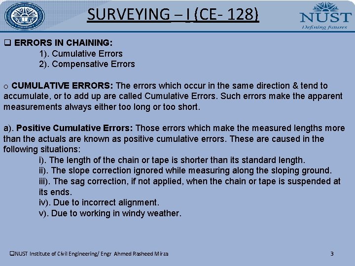
SURVEYING – I (CE- 128) q ERRORS IN CHAINING: 1). Cumulative Errors 2). Compensative Errors o CUMULATIVE ERRORS: The errors which occur in the same direction & tend to accumulate, or to add up are called Cumulative Errors. Such errors make the apparent measurements always either too long or too short. a). Positive Cumulative Errors: Those errors which make the measured lengths more than the actuals are known as positive cumulative errors. These are caused in the following situations: i). The length of the chain or tape is shorter than its standard length. ii). The slope correction ignored while measuring along the sloping ground. iii). The sag correction, if not applied, when the chain or tape is suspended at its ends. iv). Due to incorrect alignment. v). Due to working in windy weather. q. NUST Institute of Civil Engineering/ Engr Ahmed Rasheed Mirza 3
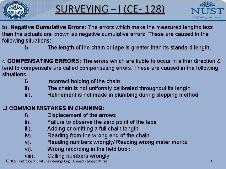
SURVEYING – I (CE- 128) b). Negative Cumulative Errors: The errors which make the measured lengths less than the actuals are known as negative cumulative errors. These are caused in the following situations: i). The length of the chain or tape is greater than its standard length. o COMPENSATING ERRORS: The errors which are liable to occur in either direction & tend to compensate are called compensating errors. These are caused in the following situations: i). Incorrect holding of the chain ii). The chain is not uniformly calibrated throughout its length iii). Refinement is not made in plumbing during stepping method q COMMON MISTAKES IN CHAINING: i). Displacement of the arrows ii). Failure to observe the zero point of the tape iii). Adding or omitting a full chain length iv). Reading from the wrong end of the chain v). Reading numbers wrongly/ Reading wrong meter marks vi). Wrong recording in the field book viii). Calling numbers wrongly q. NUST Institute of Civil Engineering/ Engr Ahmed Rasheed Mirza 4
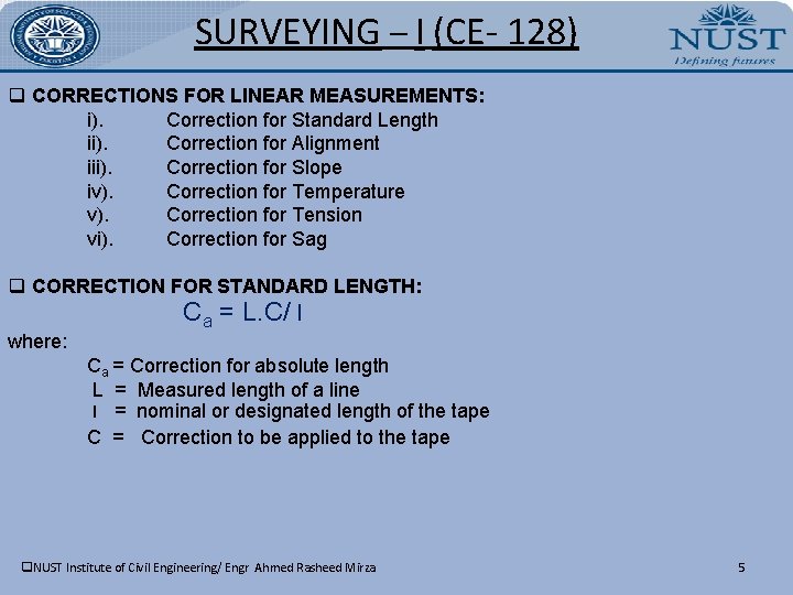
SURVEYING – I (CE- 128) q CORRECTIONS FOR LINEAR MEASUREMENTS: i). Correction for Standard Length ii). Correction for Alignment iii). Correction for Slope iv). Correction for Temperature v). Correction for Tension vi). Correction for Sag q CORRECTION FOR STANDARD LENGTH: where: Ca = L. C/ l Ca = Correction for absolute length L = Measured length of a line l = nominal or designated length of the tape C = Correction to be applied to the tape q. NUST Institute of Civil Engineering/ Engr Ahmed Rasheed Mirza 5
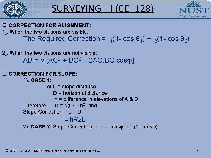
SURVEYING – I (CE- 128) q CORRECTION FOR ALIGNMENT: 1). When the two stations are visible: The Required Correction = l 1(1 - cos θ 1) + l 2(1 - cos θ 2) 2). When the two stations are not visible: AB = √ [AC 2 + BC 2 – 2 AC. BC. cosφ] q CORRECTION FOR SLOPE: 1). CASE 1: Let L = slope distance D = horizontal distance h = difference in elevations of A & B Therefore, D = √(L 2 – h 2) and Slope Correction = L – D = h 2/2 L 2). CASE 2: Slope Correction = L – L cosφ = L (1 – cosφ) q. NUST Institute of Civil Engineering/ Engr Ahmed Rasheed Mirza 6
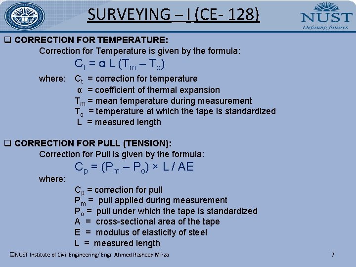
SURVEYING – I (CE- 128) q CORRECTION FOR TEMPERATURE: Correction for Temperature is given by the formula: Ct = α L (Tm – To) where: Ct = correction for temperature α = coefficient of thermal expansion Tm = mean temperature during measurement To = temperature at which the tape is standardized L = measured length q CORRECTION FOR PULL (TENSION): Correction for Pull is given by the formula: where: Cp = (Pm – Po) × L / AE Cp = correction for pull Pm = pull applied during measurement Po = pull under which the tape is standardized A = cross-sectional area of the tape E = modulus of elasticity of steel L = measured length q. NUST Institute of Civil Engineering/ Engr Ahmed Rasheed Mirza 7
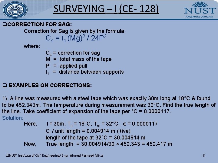
SURVEYING – I (CE- 128) q. CORRECTION FOR SAG: Correction for Sag is given by the formula: where: Cs = l 1 (Mg)2 / 24 P 2 Cs = correction for sag M = total mass of the tape P = applied pull l 1 = distance between supports q EXAMPLES ON CORRECTIONS: 1). A line was measured with a steel tape which was exactly 30 m long at 18°C & found to be 452. 343 m. The temperature during measurement was 32°C. Find the true length of the line. Take coefficient of expansion of the tape per °C = 0. 0000117. Solution: Here, l = 30 m, To = 18°C, Tm = 32°C, α = 0. 0000117 Ct / unit length = 0. 004914 m (+ive) length of the tape at 32°C = 30. 004914 m Now, True length = 30. 004914/30 × 452. 343 = 452. 417 m q. NUST Institute of Civil Engineering/ Engr Ahmed Rasheed Mirza 8
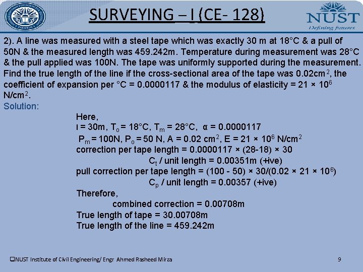
SURVEYING – I (CE- 128) 2). A line was measured with a steel tape which was exactly 30 m at 18°C & a pull of 50 N & the measured length was 459. 242 m. Temperature during measurement was 28°C & the pull applied was 100 N. The tape was uniformly supported during the measurement. Find the true length of the line if the cross-sectional area of the tape was 0. 02 cm 2, the coefficient of expansion per °C = 0. 0000117 & the modulus of elasticity = 21 × 10 6 N/cm 2. Solution: Here, l = 30 m, To = 18°C, Tm = 28°C, α = 0. 0000117 Pm = 100 N, Po = 50 N, A = 0. 02 cm 2, E = 21 × 106 N/cm 2 correction per tape length = 0. 0000117 × (28 -18) × 30 Ct / unit length = 0. 00351 m (+ive) pull correction per tape length = (100 - 50) × 30/(0. 02 × 21 × 106) Cp / unit length = 0. 00357 (+ive) Therefore, combined correction = 0. 00708 m True length of tape = 30. 00708 m True length of the line = 459. 242 m q. NUST Institute of Civil Engineering/ Engr Ahmed Rasheed Mirza 9
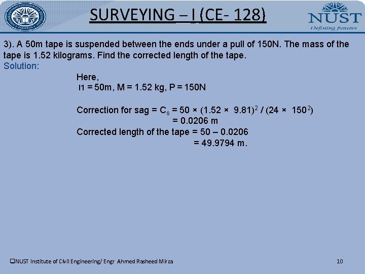
SURVEYING – I (CE- 128) 3). A 50 m tape is suspended between the ends under a pull of 150 N. The mass of the tape is 1. 52 kilograms. Find the corrected length of the tape. Solution: Here, l 1 = 50 m, M = 1. 52 kg, P = 150 N Correction for sag = Cs = 50 × (1. 52 × 9. 81)2 / (24 × 1502) = 0. 0206 m Corrected length of the tape = 50 – 0. 0206 = 49. 9794 m. q. NUST Institute of Civil Engineering/ Engr Ahmed Rasheed Mirza 10
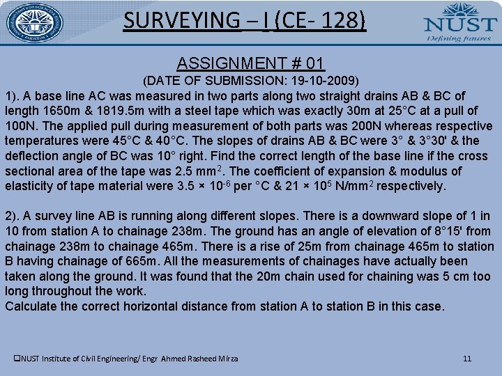
SURVEYING – I (CE- 128) ASSIGNMENT # 01 (DATE OF SUBMISSION: 19 -10 -2009) 1). A base line AC was measured in two parts along two straight drains AB & BC of length 1650 m & 1819. 5 m with a steel tape which was exactly 30 m at 25°C at a pull of 100 N. The applied pull during measurement of both parts was 200 N whereas respective temperatures were 45°C & 40°C. The slopes of drains AB & BC were 3° & 3° 30ʹ & the deflection angle of BC was 10° right. Find the correct length of the base line if the cross sectional area of the tape was 2. 5 mm 2. The coefficient of expansion & modulus of elasticity of tape material were 3. 5 × 10 -6 per °C & 21 × 105 N/mm 2 respectively. 2). A survey line AB is running along different slopes. There is a downward slope of 1 in 10 from station A to chainage 238 m. The ground has an angle of elevation of 8° 15ʹ from chainage 238 m to chainage 465 m. There is a rise of 25 m from chainage 465 m to station B having chainage of 665 m. All the measurements of chainages have actually been taken along the ground. It was found that the 20 m chain used for chaining was 5 cm too long throughout the work. Calculate the correct horizontal distance from station A to station B in this case. q. NUST Institute of Civil Engineering/ Engr Ahmed Rasheed Mirza 11
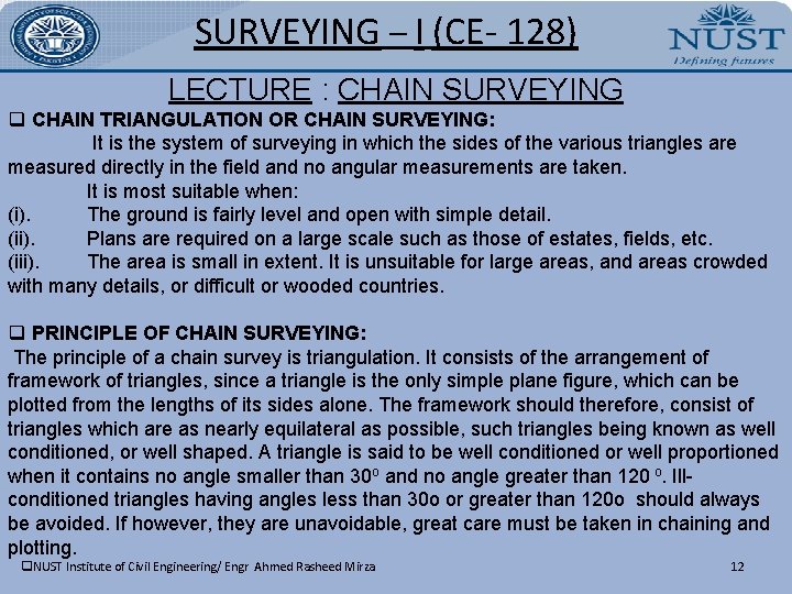
SURVEYING – I (CE- 128) LECTURE : CHAIN SURVEYING q CHAIN TRIANGULATION OR CHAIN SURVEYING: It is the system of surveying in which the sides of the various triangles are measured directly in the field and no angular measurements are taken. It is most suitable when: (i). The ground is fairly level and open with simple detail. (ii). Plans are required on a large scale such as those of estates, fields, etc. (iii). The area is small in extent. It is unsuitable for large areas, and areas crowded with many details, or difficult or wooded countries. q PRINCIPLE OF CHAIN SURVEYING: The principle of a chain survey is triangulation. It consists of the arrangement of framework of triangles, since a triangle is the only simple plane figure, which can be plotted from the lengths of its sides alone. The framework should therefore, consist of triangles which are as nearly equilateral as possible, such triangles being known as well conditioned, or well shaped. A triangle is said to be well conditioned or well proportioned when it contains no angle smaller than 30 o and no angle greater than 120 o. Illconditioned triangles having angles less than 30 o or greater than 120 o should always be avoided. If however, they are unavoidable, great care must be taken in chaining and plotting. q. NUST Institute of Civil Engineering/ Engr Ahmed Rasheed Mirza 12
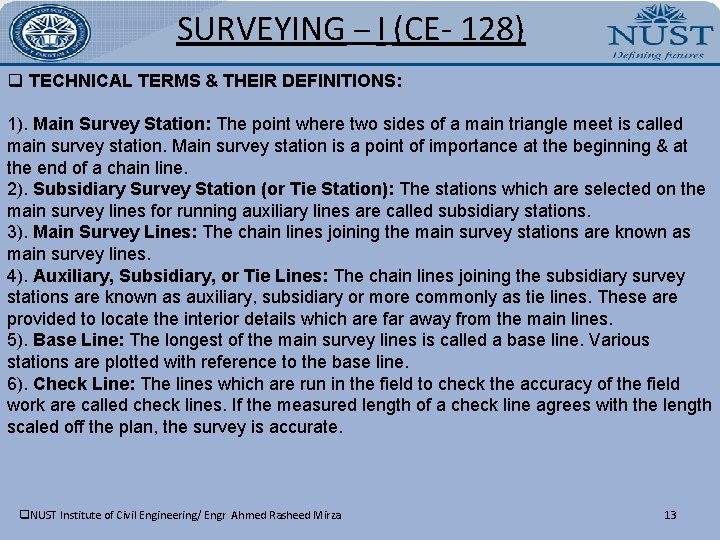
SURVEYING – I (CE- 128) q TECHNICAL TERMS & THEIR DEFINITIONS: 1). Main Survey Station: The point where two sides of a main triangle meet is called main survey station. Main survey station is a point of importance at the beginning & at the end of a chain line. 2). Subsidiary Survey Station (or Tie Station): The stations which are selected on the main survey lines for running auxiliary lines are called subsidiary stations. 3). Main Survey Lines: The chain lines joining the main survey stations are known as main survey lines. 4). Auxiliary, Subsidiary, or Tie Lines: The chain lines joining the subsidiary survey stations are known as auxiliary, subsidiary or more commonly as tie lines. These are provided to locate the interior details which are far away from the main lines. 5). Base Line: The longest of the main survey lines is called a base line. Various stations are plotted with reference to the base line. 6). Check Line: The lines which are run in the field to check the accuracy of the field work are called check lines. If the measured length of a check line agrees with the length scaled off the plan, the survey is accurate. q. NUST Institute of Civil Engineering/ Engr Ahmed Rasheed Mirza 13
SURVEYING – I (CE- 128) q SELECTION OF STATIONS: The following points should be kept in mind while selecting survey stations: 1). Main survey stations at the ends of chain lines should be intervisible. 2). Survey lines should be minimum possible. 3). The main principle of surveying viz. , working from the whole to the part & not from the part to the whole, should be strictly observed. 4). Survey stations should form well conditioned triangles. 5). Every triangle should be provided with a check line. 6). Tie lines should be provided to off long offsets. 7). Obstacles to ranging & chaining, if any, should be avoided. 8). The larger side of the triangle should be placed parallel to boundaries, roads, buildings etc. to have short offsets. 9). To avoid trespassing, main survey lines should remain within the boundaries of the property to be surveyed. 10). Chain lines should be preferably over level ground. 11). Lines should be laid on one side of the road to avoid interruption of changing by passing traffic. q. NUST Institute of Civil Engineering/ Engr Ahmed Rasheed Mirza 14
SURVEYING – I (CE- 128) q SELECTION & MEASUREMENT OF THE BASE LINE: In chain surveying, the base line is the most important line as it fixes the directions of all other chain lines. The following points are kept in view during its selection & measurement: 1). It should be laid preferably on a level ground. 2). It should be run through the centre of the length of the area. 3). It should be correctly measured horizontally. 4). It should be measured twice or thrice & the mean distance accepted, as its correct length. 5). Great care should be taken, to ensure straightness of the base line. 6). If convenient, two base lines perpendicular bisecting each other should be laid out. q OFFSETS: In chain surveying, the position of details i. e. boundaries, culverts, roads, stream bends etc. , are located with respect to the chain line by measuring their distances right or left of the chain lines, such lateral measurements are called offsets. There are two types of offsets: Perpendicular Offsets & Oblique Offsets Depending upon the length, offsets are further classified as short offset (length less than 15 m) & long offsets (length more than 15 m). q. NUST Institute of Civil Engineering/ Engr Ahmed Rasheed Mirza 15
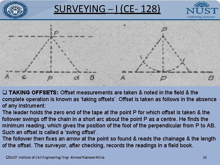
SURVEYING – I (CE- 128) q TAKING OFFSETS: Offset measurements are taken & noted in the field & the complete operation is known as ‘taking offsets’. Offset is taken as follows in the absence of any instrument: The leader holds the zero end of the tape at the point P for which offset is taken & the follower swings off the chain in a short arc about the point P as a centre. He finds the minimum reading, which gives the position of the foot of the perpendicular from P to AB. Such an offset is called a ‘swing offset’. The follower then fixes an arrow at the point so found & reads the chainage & the length of the offset. The surveyor, after checking, records the readings in a field book. q. NUST Institute of Civil Engineering/ Engr Ahmed Rasheed Mirza 16
SURVEYING – I (CE- 128) q INSTRUMENTS FOR SETTING OUT RIGHT ANGLES: 1). Cross Staffs 2). Optical Squares q FIELD BOOK: The book in which chainages, offset measurements & sketches of detail points are recorded is generally called a field book. It is an oblong book of size 20 cm × 12 cm & opens lengthwise. 1). BOOKING FIELD NOTES: In a field book, field notes are entered from the bottom of the page upward. At the beginning of a chain line, the following information is recorded in the field book: * The name or number of the chain line * The name or number of the survey station * The symbol denoting the station mark * The direction of survey lines starting off from or ending at the station * The initial chainage which is generally zero, is enclosed in the symbol. All distances along the chain line i. e. chainages are entered on the central line or in the central column & offsets are written opposite to them on the right or left of the column according to their ground positions with respect to the chain line. Close to the q. NUST Institute of Civil Engineering/ Engr Ahmed Rasheed Mirza 17
SURVEYING – I (CE- 128) offsets, their sketches are drawn to guide the draftsman to draw them correctly. Tie or subsidiary stations along a chain line should be indicated by a circleor an oval around their chainages. A specimen field book for chain survey is shown below. q. NUST Institute of Civil Engineering/ Engr Ahmed Rasheed Mirza 18
SURVEYING – I (CE- 128) 2). INSTRUCTIONS FOR BOOKING THE FIELD NOTES: § Each chain line or a tie line, should be recorded on a separate page. § The recorder should always face the direction of chaining while booking the field notes. § All the measurements should be recorded as soon as these are taken & nothing should be left to memory. § The notes should be complete, neat & accurate with all information necessary for plotting the survey by a draftsman in office. § Numerals should be neatly & legibly written without any overwriting. § Sketches of the details should be neat & clear. § A good quality pencil should be used for recording the entries. § The field book is an important document & should be kept clean. Wrong entries should be scored out & correct ones written over the wrong ones. If an entire page is to be discarded, it should be crossed, & marked “cancelled”. A reference to the page on which correct readings are recorded, is made on this page. § The complete record of the chain survey should include: - A general layout plan of the lines - The details of the lines - The date of the survey - A page index of the lines - Names of the surveyor & his assistants q. NUST Institute of Civil Engineering/ Engr Ahmed Rasheed Mirza 19
SURVEYING – I (CE- 128) q FIELD WORK: - Reconnaissance - Marking Stations - Running Survey Lines - REFERENCE SKETCH: The sketch, showing at least measurements to three permanent & definite points such as gates, pillars, light posts, corner of buildings etc. , is known as a reference or location sketch. q. NUST Institute of Civil Engineering/ Engr Ahmed Rasheed Mirza 20