Simulation of Longitudinal and Transverse Impedance of TCDD


- Slides: 13

Simulation of Longitudinal and Transverse Impedance of TCDD (original geometry) A. Grudiev B. 28. 10. 2005

TCDD geometry (original proposal)

TCDD geometry (original proposal) closed open

Longitudinal Impedance from Gdfid. L Mode#1 Mode#2

Longitudinal Impedance from Gdfid. L Z/n = 13. 5 mΩ Z/n = 10. 1 mΩ LHC total broad band longitudinal impedance ~ 70 mΩ

Longitudinal impedance from HFSS Mode#1 f = 78. 5 MHz, Q=6320, rl/Q = 157. 5 LinacΩ, kl = 19. 4 V/n. C For LHC beam: 80 mm x 16 n. C x 40 MHz and assuming f = 80 MHz: Ploss ~ 400 k. W

Longitudinal impedance from HFSS Mode#2 f = 648 MHz, Q=18400, rl/Q = 21 LinacΩ, kl = 21. 6 V/n. C For LHC beam: 80 mm x 16 n. C x 40 MHz and assuming f = 680 MHz: Ploss ~ 44 k. W

Transverse Impedance from Gdfid. L Mode#1

Transverse Impedance from Gdfid. L LHC total broad band transverse impedance ~ 2000 kΩ/m Zy = 12 kΩ/m

Transverse impedance from HFSS Mode#1 f = 54. 8 MHz, Q=4870, rt/Q = 20200 LinacΩ/m, kt = 1800 V/n. C/m, Rt = 49. 2 MΩ/m

Vertical tune shift LHC injection pars: E=450 Ge. V σz = 115 mm N = 1011 f 0 = 11. 2455 k. Hz Qy = 59. 31 ξ=0

Vertical tune shift

Recommendations • To avoid transverse mode#1 rf contact between upper and lower parts of the absorber is necessary • To avoid longitudinal mode#1 rf contact between beam pipe aperture and absorber aperture is necessary on each side • To reduce broad band impedance smooth (~15 o) transition from beam pipe aperture (round) to absorber aperture (rectangular) is necessary on each side
 Vector impedance meter block diagram
 Compression and rarefaction
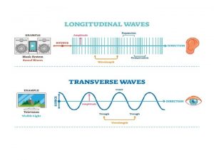
 Difference between transverse wave and longitudinal wave
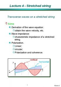
 Transverse impedance of a string
 Longitudinal and transverse framing system
 Double bottom plate framing
 Medium of a wave
 Wavelength formula triangle
 Tcdd emniyet yönetim sistemi
 Siemens velaro tcdd
 Tcdd outlook
 Tcdd
Tcdd Light is electromagnetic radiation true or false
 Transverse vs longitudinal waves
