PARARI AUSTRALIAN EXPLOSIVE ORDNANCE SAFETY SYMPOSIUM 2019 AN



- Slides: 20
PARARI AUSTRALIAN EXPLOSIVE ORDNANCE SAFETY SYMPOSIUM 2019 AN OVERVIEW OF PERSONNEL-BORNE ELECTROSTATIC DISCHARGE PARAMETERS THINUS NEETHLING, EEH DESK OFFICER, EXPLOSIVE MATERIEL BRANCH, JSD, CASG 1
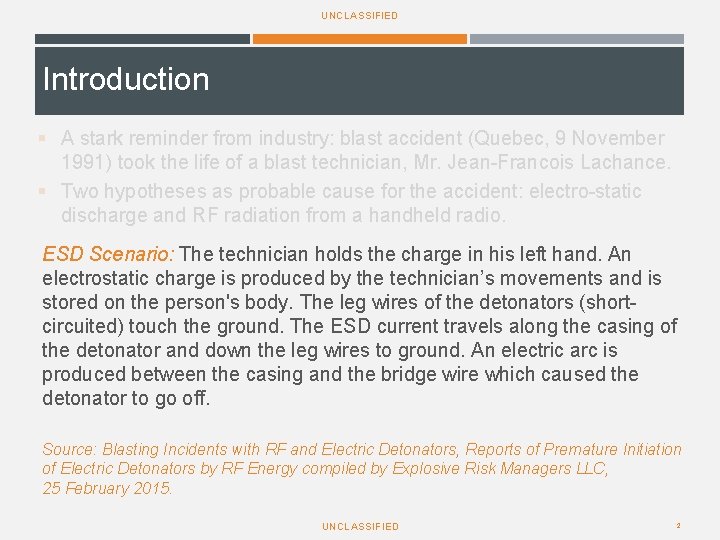
UNCLASSIFIED Introduction § A stark reminder from industry: blast accident (Quebec, 9 November 1991) took the life of a blast technician, Mr. Jean-Francois Lachance. § Two hypotheses as probable cause for the accident: electro-static discharge and RF radiation from a handheld radio. ESD Scenario: The technician holds the charge in his left hand. An electrostatic charge is produced by the technician’s movements and is stored on the person's body. The leg wires of the detonators (shortcircuited) touch the ground. The ESD current travels along the casing of the detonator and down the leg wires to ground. An electric arc is produced between the casing and the bridge wire which caused the detonator to go off. Source: Blasting Incidents with RF and Electric Detonators, Reports of Premature Initiation of Electric Detonators by RF Energy compiled by Explosive Risk Managers LLC, 25 February 2015. UNCLASSIFIED 2
UNCLASSIFIED ESD parameters for EO testing/assessment § Ordnance systems shall not be inadvertently initiated or dudded when subjected to 25 k. V discharged from a 500 p. F capacitor via a 500Ω and/or 5 kΩ series resistor, with a circuit inductance of ≤ 5µH. § Further requirements: - incrementing & decrementing test voltages - dual polarity testing § Baseline PESD parameters published in MIL-STD-331 A of 15 October 1976 UNCLASSIFIED 3
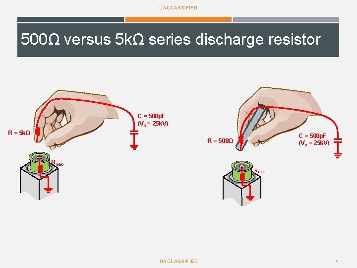
UNCLASSIFIED 500Ω versus 5 kΩ series discharge resistor C = 500 p. F (V 0 = 25 k. V) R = 5 kΩ C = 500 p. F (V 0 = 25 k. V) R = 500Ω REED UNCLASSIFIED 4
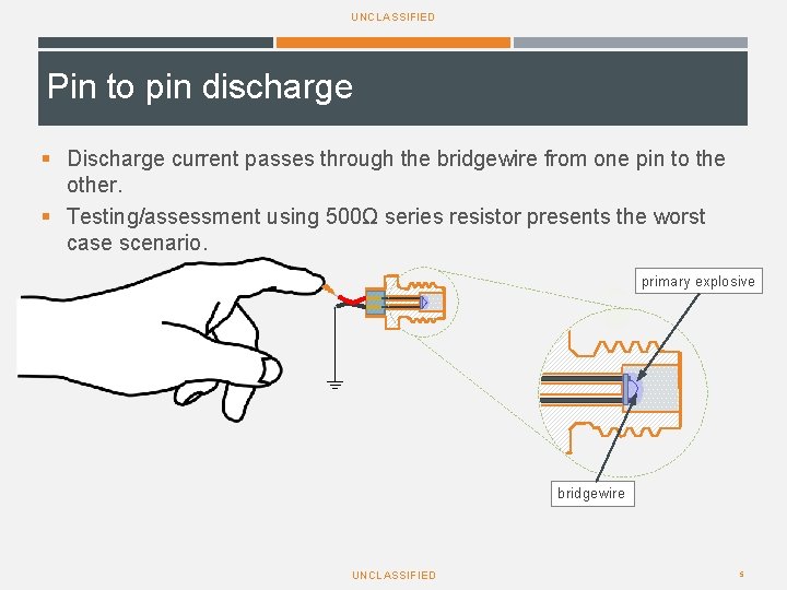
UNCLASSIFIED Pin to pin discharge § Discharge current passes through the bridgewire from one pin to the other. § Testing/assessment using 500Ω series resistor presents the worst case scenario. primary explosive bridgewire UNCLASSIFIED 5
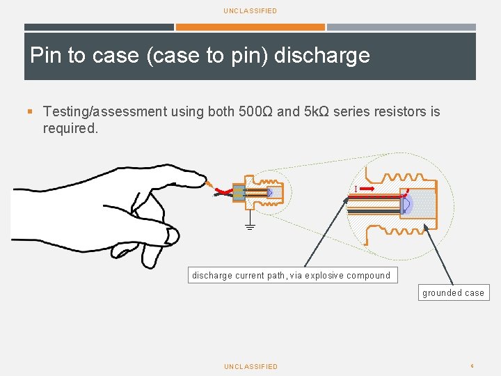
UNCLASSIFIED Pin to case (case to pin) discharge § Testing/assessment using both 500Ω and 5 kΩ series resistors is required. I discharge current path, via explosive compound grounded case UNCLASSIFIED 6
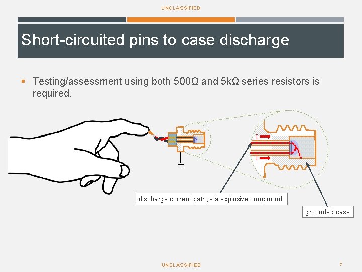
UNCLASSIFIED Short-circuited pins to case discharge § Testing/assessment using both 500Ω and 5 kΩ series resistors is required. I I discharge current path, via explosive compound grounded case UNCLASSIFIED 7
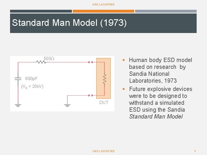
UNCLASSIFIED Standard Man Model (1973) 500Ω 600 p. F (V 0 = 20 k. V) DUT UNCLASSIFIED § Human body ESD model based on research by Sandia National Laboratories, 1973 § Future explosive devices were to be designed to withstand a simulated ESD using the Sandia Standard Man Model 8
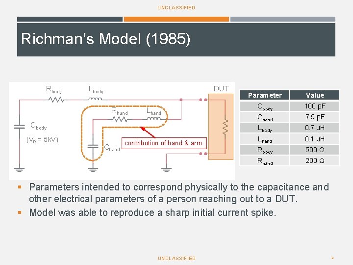
UNCLASSIFIED Richman’s Model (1985) Rbody Lbody DUT Rhand Lhand Cbody (V = 25 k. V) (V 00 = 5 k. V) Chand contribution of hand & arm Parameter Value Cbody 100 p. F Chand 7. 5 p. F Lbody 0. 7 μH Lhand 0. 1 μH Rbody 500 Ω Rhand 200 Ω § Parameters intended to correspond physically to the capacitance and other electrical parameters of a person reaching out to a DUT. § Model was able to reproduce a sharp initial current spike. UNCLASSIFIED 9
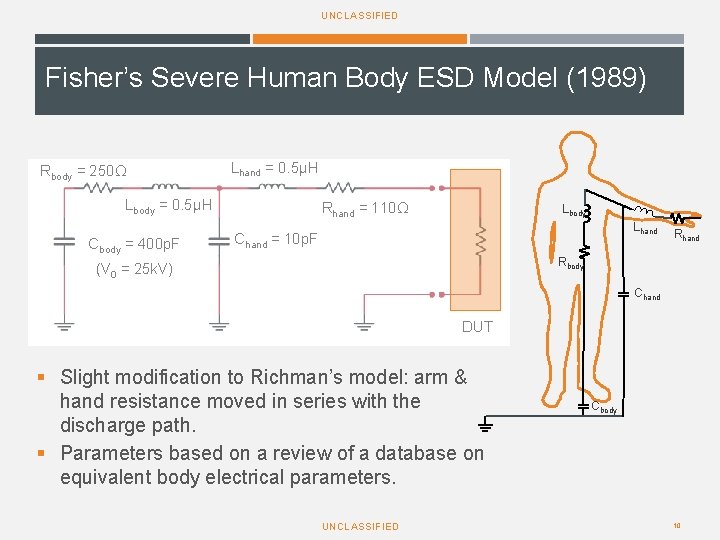
UNCLASSIFIED Fisher’s Severe Human Body ESD Model (1989) Rbody = 250Ω Lhand = 0. 5μH Lbody = 0. 5μH Cbody = 400 p. F Rhand = 110Ω Lbody Lhand Chand = 10 p. F Rhand Rbody (V 0 = 25 k. V) Chand DUT § Slight modification to Richman’s model: arm & hand resistance moved in series with the discharge path. § Parameters based on a review of a database on equivalent body electrical parameters. UNCLASSIFIED Cbody 10
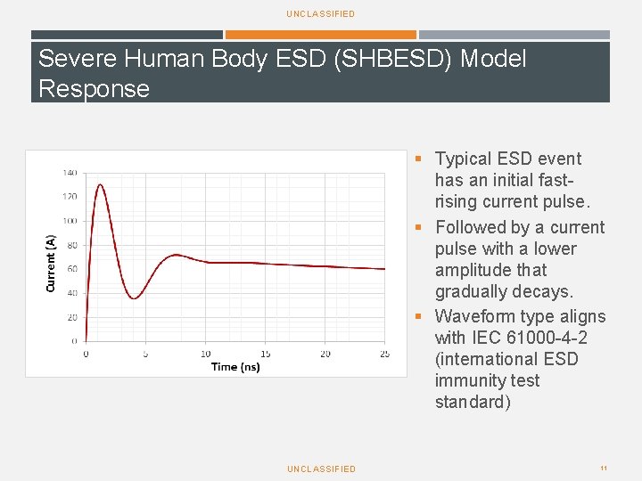
UNCLASSIFIED Severe Human Body ESD (SHBESD) Model Response § Typical ESD event has an initial fastrising current pulse. § Followed by a current pulse with a lower amplitude that gradually decays. § Waveform type aligns with IEC 61000 -4 -2 (international ESD immunity test standard) UNCLASSIFIED 11
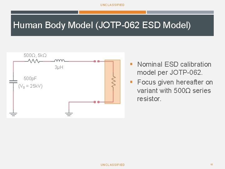
UNCLASSIFIED Human Body Model (JOTP-062 ESD Model) 500Ω, 5 kΩ § Nominal ESD calibration model per JOTP-062. § Focus given hereafter on variant with 500Ω series resistor. 3μH 500 p. F (V 0 = 25 k. V) UNCLASSIFIED 12
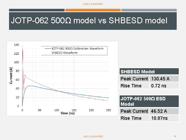
UNCLASSIFIED JOTP-062 500Ω model vs SHBESD model SHBESD Model Peak Current 130. 45 A Rise Time 0. 72 ns JOTP-062 500Ω ESD Model Peak Current 46. 52 A Rise Time 10. 87 ns UNCLASSIFIED 13
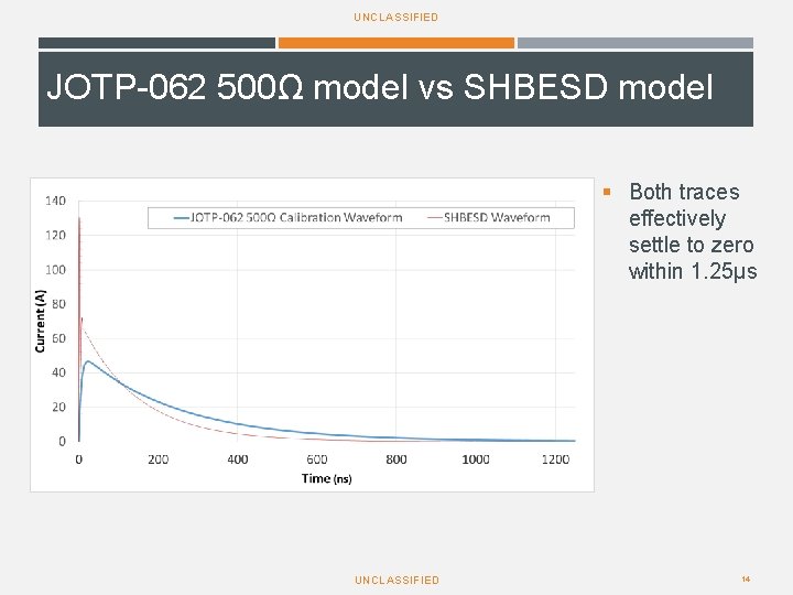
UNCLASSIFIED JOTP-062 500Ω model vs SHBESD model § Both traces effectively settle to zero within 1. 25μs UNCLASSIFIED 14
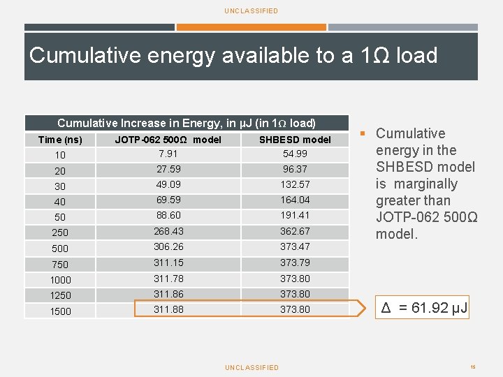
UNCLASSIFIED Cumulative energy available to a 1Ω load Cumulative Increase in Energy, in µJ (in 1Ω load) Time (ns) 10 JOTP-062 500Ω model 7. 91 SHBESD model 54. 99 20 27. 59 96. 37 30 49. 09 132. 57 40 69. 59 164. 04 50 88. 60 191. 41 250 268. 43 362. 67 500 306. 26 373. 47 750 311. 15 373. 79 1000 311. 78 373. 80 1250 311. 86 373. 80 1500 311. 88 373. 80 UNCLASSIFIED § Cumulative energy in the SHBESD model is marginally greater than JOTP-062 500Ω model. Δ = 61. 92 μJ 15
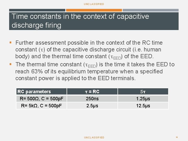
UNCLASSIFIED Time constants in the context of capacitive discharge firing § Further assessment possible in the context of the RC time constant (τ) of the capacitive discharge circuit (i. e. human body) and thermal time constant (τEED) of the EED. § The thermal time constant (τEED) is the time it takes the EED to reach 63% of its equilibrium temperature when a specified constant power is applied to the EED terminals. RC parameters R= 500Ω, C = 500 p. F R= 5 kΩ, C = 500 p. F τ = RC 250 ns 2. 5µs UNCLASSIFIED 5τ 1. 25μs 12. 5μs 16
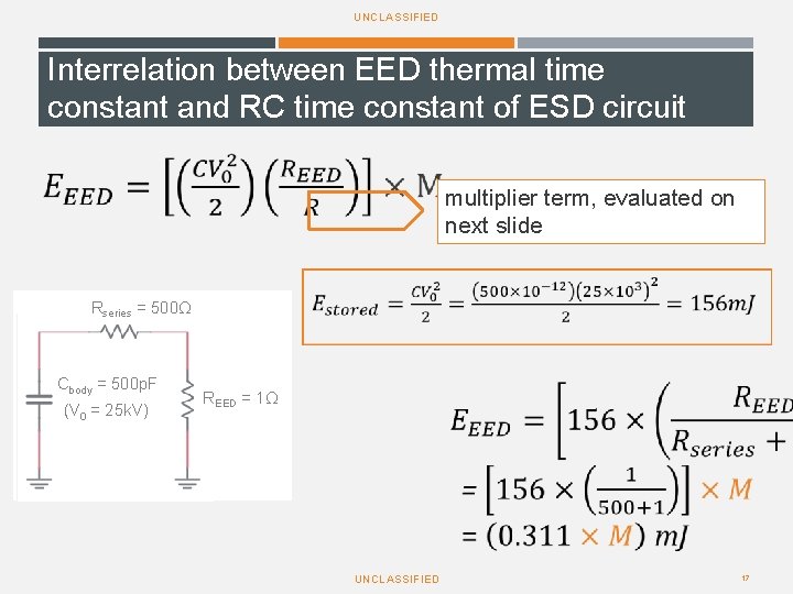
UNCLASSIFIED Interrelation between EED thermal time constant and RC time constant of ESD circuit multiplier term, evaluated on next slide Rseries = 500Ω Cbody = 500 p. F (V 0 = 25 k. V) REED = 1Ω UNCLASSIFIED 17
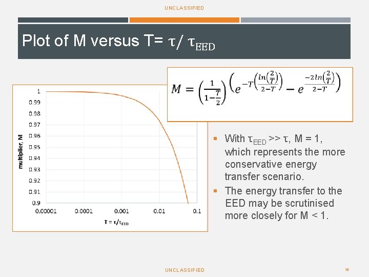
UNCLASSIFIED Plot of M versus T= τ/ τEED § With τEED >> τ, M = 1, which represents the more conservative energy transfer scenario. § The energy transfer to the EED may be scrutinised more closely for M < 1. UNCLASSIFIED 18
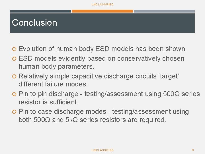
UNCLASSIFIED Conclusion Evolution of human body ESD models has been shown. ESD models evidently based on conservatively chosen human body parameters. Relatively simple capacitive discharge circuits ‘target’ different failure modes. Pin to pin discharge - testing/assessment using 500Ω series resistor is sufficient. Pin to case discharge modes - testing/assessment using both 500Ω and 5 kΩ series resistors are required. UNCLASSIFIED 19
UNCLASSIFIED Questions? UNCLASSIFIED 20