MORE ON ALTERNATING CURRENT Physics WHAT IS ALTERNATING

, is an electric current in which the")


 by alternating voltages. An")
 = v^2(t)/R where")
=Vpeaksin(wt) i(t)=v(t)/R=Vpeaksin(wt)/R P(t)=v(t) i(t)=(Vpeak)^2/R. sin^2(w t) By the following trigonometric identity, the")


- Slides: 12
MORE ON ALTERNATING CURRENT Physics
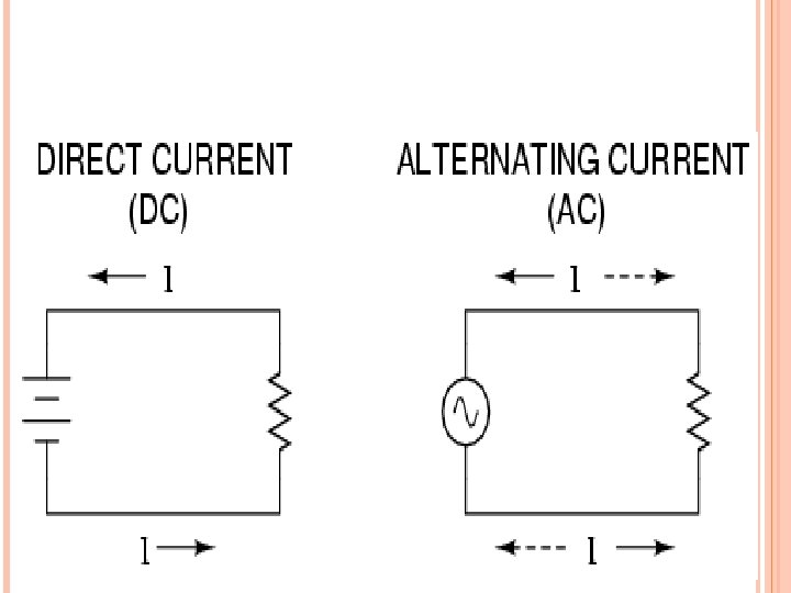
WHAT IS ALTERNATING CURRENT? Alternating current (AC), is an electric current in which the flow of electric charge periodically reverses direction, whereas in direct current (DC, also dc), the flow of electric charge is only in one direction. AC is the form in which electric power is delivered to businesses and residences. The usual waveform of alternating current in most electric power circuits is a sine wave. In certain applications, different waveforms are used, such as triangular or square waves.
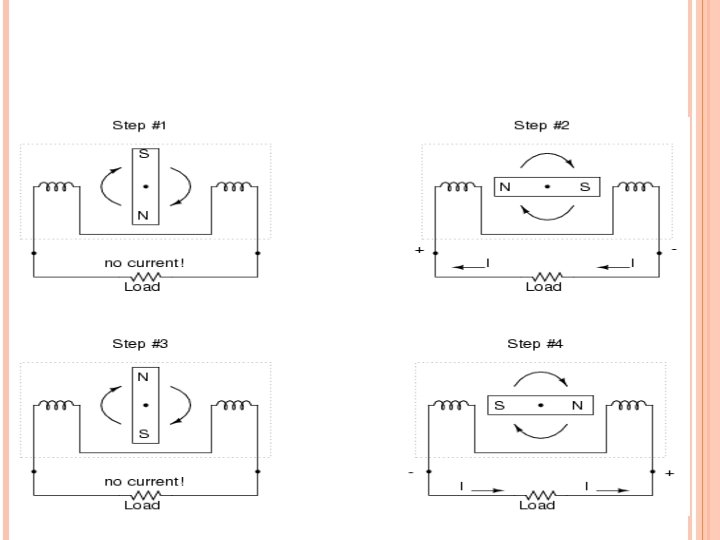
WHY A. C. ? One might wonder why anyone would bother with such a thing as AC. It is true that in some cases AC holds no practical advantage over DC. In applications where electricity is used to dissipate energy in the form of heat, the polarity or direction of current is irrelevant, so long as there is enough voltage and current to the load to produce the desired heat (power dissipation). However, with AC it is possible to build electric generators, motors and power distribution systems that are far more efficient than DC, and so we find AC used predominately across the world in high power applications. To explain the details of why this is so, a bit of background knowledge about AC is necessary. If a machine is constructed to rotate a magnetic field around a set of stationary wire coils with the turning of a shaft, AC voltage will be produced across the wire coils as that shaft is rotated, in accordance with Faraday’s Law of electromagnetic induction. This is the basic operating principle of an AC generator, also known as an alternator: Figure on next page…
TRANSMISSION, DISTRIBUTION, AND DOMESTIC POWER SUPPLY The reason that electric power is distributed as alternating current is that AC voltage may be increased or decreased with a transformer. This allows the power to be transmitted through power lines efficiently at high voltage, which reduces the power lost as heat due to resistance of the wire, and the voltage to be reduced to safe levels for use by the customer. Use of a higher voltage leads to significantly more efficient transmission of power. The power losses (PL) in a conductor are a product of the square of the current (I) and the resistance (R) of the conductor, described by the formula P L = I^2 R This means that when transmitting a fixed power on a given wire, if the current is doubled, the power loss will be four times greater. The power transmitted is equal to the product of the current and the voltage (assuming no phase difference); that is, PT = IV Thus, the same amount of power can be transmitted with a lower current by increasing the voltage. It is therefore advantageous when transmitting large amounts of power to distribute the power with high voltages (often hundreds of kilovolts).
AC POWER SUPPLY FREQUENCIES The frequency of the electrical system varies by country and sometimes within a country; most electric power is generated at either 50 or 60 hertz. Some countries have a mixture of 50 Hz and 60 Hz supplies, notably electricity power transmission in Japan. A low frequency eases the design of electric motors, particularly for hoisting, crushing and rolling applications, and commutator-type traction motors for applications such as railways. However, low frequency also causes noticeable flicker in arc lamps and incandescent light bulbs. The use of lower frequencies also provided the advantage of lower impedance losses, which are proportional to frequency. The original Niagara Falls generators were built to produce 25 Hz power, as a compromise between low frequency for traction and heavy induction motors, while still allowing incandescent lighting to operate (although with noticeable flicker). Most of the 25 Hz residential and commercial customers for Niagara Falls power were converted to 60 Hz by the late 1950 s, although some[which? ] 25 Hz industrial customers still existed as of the start of the 21 st century. 16. 7 Hz power (formerly 16 2/3 Hz) is still used in some European rail systems, such as in Austria, Germany, Norway, Sweden and Switzerland. Off-shore, military, textile industry, marine, aircraft, and spacecraft applications sometimes use 400 Hz, for benefits of reduced weight of apparatus or higher motor speeds. Computer mainframe systems are often powered by 415 Hz, using customer-supplied 35 or 70 KVA motor-generator sets. [3] Smaller mainframes may have an internal 415 Hz M-G set. In any case, the input to the M-G set is the local customary voltage and frequency, variously 200 (Japan), 208, 240 (North America), 380, 400 or 415 (Europe) volts, and variously 50 or 60
MATHEMATICS OF AC VOLTAGES Alternating currents are accompanied (or caused) by alternating voltages. An AC voltage v can be described mathematically as a function of time by the following equation: v(t)=Vpeak. sin(w t), where V peak is the peak voltage (unit: volt), w is the angular frequency (unit: radians per second) The angular frequency is related to the physical frequency, f (unit = hertz), which represents the number of cycles per second, by the equation w = 2∏f. t is the time (unit: second). The peak-to-peak value of an AC voltage is defined as the difference between its positive peak and its negative peak. Since the maximum value of sin(x) is +1 and the minimum value is − 1, an AC voltage swings between +Vpeak and -Vpeak. The peak-to-peak voltage, usually written as Vpp or VP-P, is therefore Vpeak- (-Vpeak) = 2 Vpeak
POWER The relationship between voltage and the power delivered is p(t) = v^2(t)/R where R represents a load resistance. Rather than using instantaneous power, p(t), it is more practical to use a time averaged power (where the averaging is performed over any integer number of cycles). Therefore, AC voltage is often expressed as a root mean square (RMS) value, written as Vrms, because Ptime averaged = V^2 rms/R.
POWER OSCILLATION v(t)=Vpeaksin(wt) i(t)=v(t)/R=Vpeaksin(wt)/R P(t)=v(t) i(t)=(Vpeak)^2/R. sin^2(w t) By the following trigonometric identity, the power oscillation is double frequency of the voltage. sin^2 x = (1 - cos 2 x)/2
MCQ 1. A sawtooth wave has a period of 10 ms. Its frequency is a. 10 Hz b. 1000 Hz c. 50 Hz d. 100 Hz 2. A sinusoidal current has an rms value of 14 m. A. The peak-to-peak value is a. 39. 6 m. A b. 16 m. A c. 45. 12 m. A d. 22. 6 m. A
THANK YOU Created by Prof. Swapan Kumar Gupta