MicroResearch Finland Oy Timing System Modules Jukka Pietarinen

- Slides: 18
Micro-Research Finland Oy Timing System Modules Jukka Pietarinen EPICS Collaboration Meeting, Argonne, June 2006
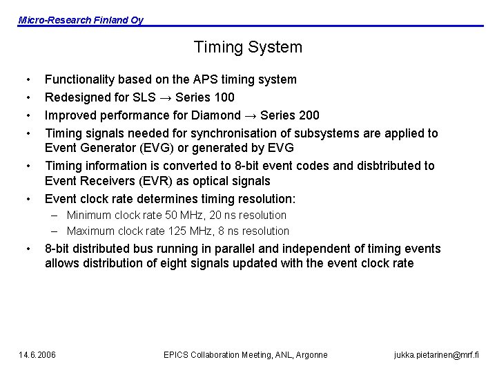
Micro-Research Finland Oy Timing System • • • Functionality based on the APS timing system Redesigned for SLS → Series 100 Improved performance for Diamond → Series 200 Timing signals needed for synchronisation of subsystems are applied to Event Generator (EVG) or generated by EVG Timing information is converted to 8 -bit event codes and disbtributed to Event Receivers (EVR) as optical signals Event clock rate determines timing resolution: – Minimum clock rate 50 MHz, 20 ns resolution – Maximum clock rate 125 MHz, 8 ns resolution • 8 -bit distributed bus running in parallel and independent of timing events allows distribution of eight signals updated with the event clock rate 14. 6. 2006 EPICS Collaboration Meeting, ANL, Argonne jukka. pietarinen@mrf. fi
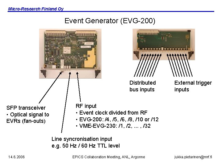
Micro-Research Finland Oy Event Generator (EVG-200) Distributed bus inputs SFP transceiver • Optical signal to EVRs (fan-outs) External trigger inputs RF input • Event clock divided from RF • EVG-200: /4, /5, /6, /8, /10 or /12 • VME-EVG-230: /1, /2, . . . , /32 Line syncronisation input e. g. 50 Hz / 60 Hz TTL level 14. 6. 2006 EPICS Collaboration Meeting, ANL, Argonne jukka. pietarinen@mrf. fi
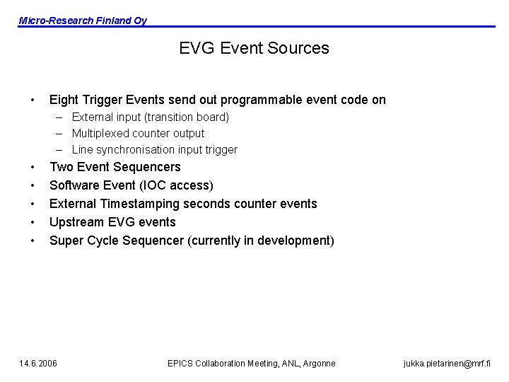
Micro-Research Finland Oy EVG Event Sources • Eight Trigger Events send out programmable event code on – External input (transition board) – Multiplexed counter output – Line synchronisation input trigger • • • Two Event Sequencers Software Event (IOC access) External Timestamping seconds counter events Upstream EVG events Super Cycle Sequencer (currently in development) 14. 6. 2006 EPICS Collaboration Meeting, ANL, Argonne jukka. pietarinen@mrf. fi
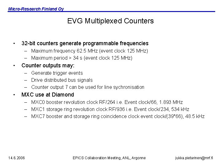
Micro-Research Finland Oy EVG Multiplexed Counters • 32 -bit counters generate programmable frequencies – Maximum frequency 62. 5 MHz (event clock 125 MHz) – Maximum period > 34 s (event clock 125 MHz) • Counter outputs may: – Generate trigger events – Drive distributed bus signals – Counter output 7 can be used for line sychronisation • MXC use at Diamond – MXC 0 booster revolution clock RF/264 i. e. Event clock/66, 1. 893 MHz – MXC 1 storage ring revolution clock RF/936 i. e. Event clock/234, 534 k. Hz – MXC 7 booster and storage ring coincidence clock event clock/(39*66), 48. 5 k. Hz 14. 6. 2006 EPICS Collaboration Meeting, ANL, Argonne jukka. pietarinen@mrf. fi
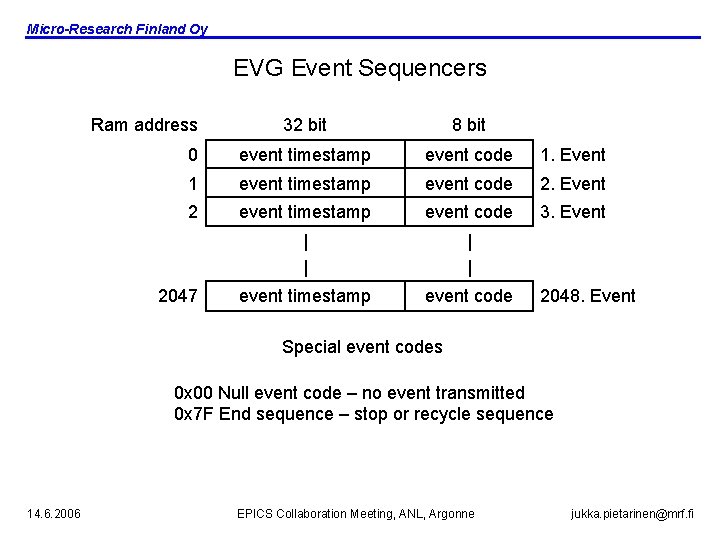
Micro-Research Finland Oy EVG Event Sequencers Ram address 32 bit 8 bit 0 event timestamp event code 1. Event 1 event timestamp event code 2. Event 2 event timestamp event code 3. Event | | event timestamp event code 2047 2048. Event Special event codes 0 x 00 Null event code – no event transmitted 0 x 7 F End sequence – stop or recycle sequence 14. 6. 2006 EPICS Collaboration Meeting, ANL, Argonne jukka. pietarinen@mrf. fi
Micro-Research Finland Oy EVG Event Sequencer Triggering • • SW trigger External input Multiplexed counter output Line synchronisation triggering Line Sync. input Programmable Divider /1 to /256 Phase shifter 0 to 25. 5 ms in 0. 1 ms steps D MXC 7 Q Trigger Event clock 14. 6. 2006 EPICS Collaboration Meeting, ANL, Argonne jukka. pietarinen@mrf. fi
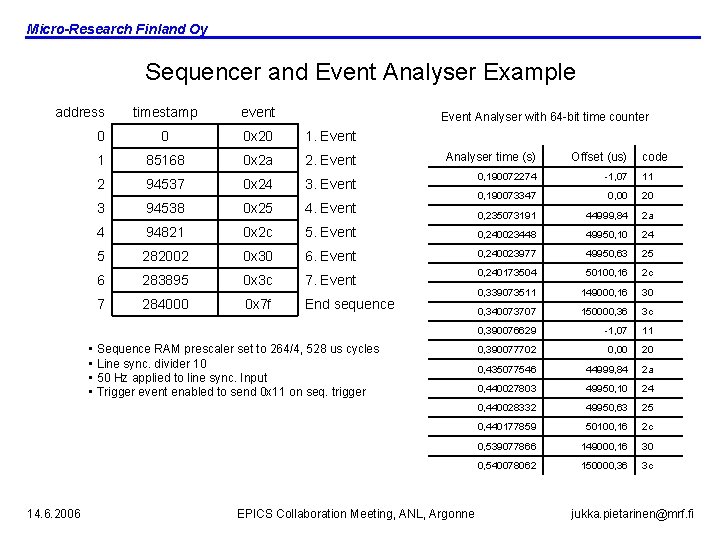
Micro-Research Finland Oy Sequencer and Event Analyser Example address timestamp event 0 0 0 x 20 1. Event 1 85168 0 x 2 a 2. Event 2 94537 0 x 24 3. Event 3 94538 0 x 25 4. Event 4 94821 0 x 2 c 5 282002 6 7 Event Analyser with 64 -bit time counter Analyser time (s) Offset (us) 0, 190072274 -1, 07 11 0, 190073347 0, 00 20 0, 235073191 44999, 84 2 a 5. Event 0, 240023448 49950, 10 24 0 x 30 6. Event 0, 240023977 49950, 63 25 283895 0 x 3 c 7. Event 0, 240173504 50100, 16 2 c 284000 0 x 7 f End sequence 0, 339073511 149000, 16 30 0, 340073707 150000, 36 3 c 0, 390076629 -1, 07 11 0, 390077702 0, 00 20 0, 435077546 44999, 84 2 a 0, 440027803 49950, 10 24 0, 440028332 49950, 63 25 0, 440177859 50100, 16 2 c 0, 539077866 149000, 16 30 0, 540078062 150000, 36 3 c • Sequence RAM prescaler set to 264/4, 528 us cycles • Line sync. divider 10 • 50 Hz applied to line sync. Input • Trigger event enabled to send 0 x 11 on seq. trigger 14. 6. 2006 EPICS Collaboration Meeting, ANL, Argonne code jukka. pietarinen@mrf. fi
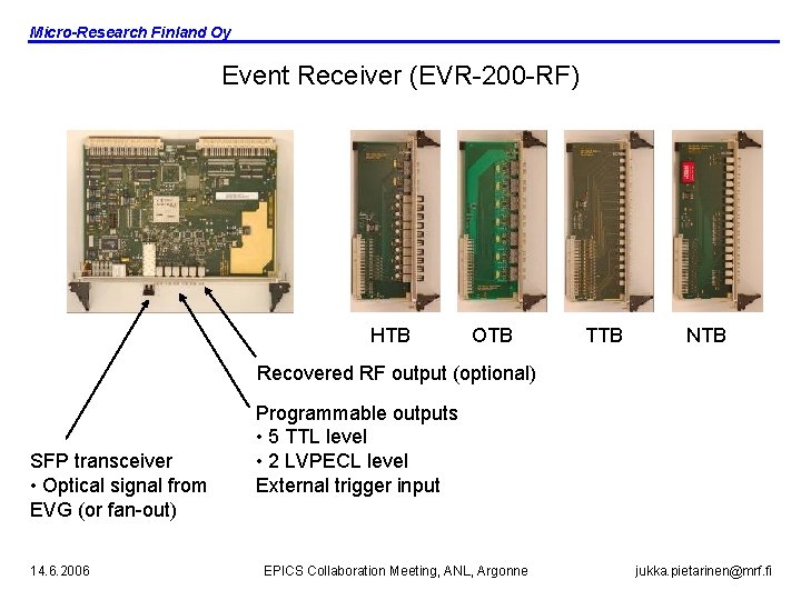
Micro-Research Finland Oy Event Receiver (EVR-200 -RF) HTB OTB TTB NTB Recovered RF output (optional) SFP transceiver • Optical signal from EVG (or fan-out) 14. 6. 2006 Programmable outputs • 5 TTL level • 2 LVPECL level External trigger input EPICS Collaboration Meeting, ANL, Argonne jukka. pietarinen@mrf. fi
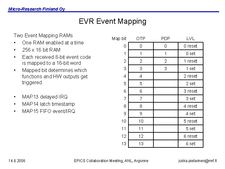
Micro-Research Finland Oy EVR Event Mapping Two Event Mapping RAMs • One RAM enabled at a time • 256 x 16 bit RAM • Each received 8 -bit event code is mapped to a 16 -bit word • Mapped bit determines which functions and HW outputs get triggered • • • MAP 13 delayed IRQ MAP 14 latch timestamp MAP 15 FIFO event/IRQ 14. 6. 2006 Map bit OTP PDP LVL 0 0 reset 1 1 1 0 set 2 2 2 1 reset 3 3 3 1 set 4 4 2 reset 5 5 2 set 6 6 3 reset 7 7 3 set 8 8 4 reset 9 9 4 set 10 10 5 reset 11 11 5 set 12 12 6 reset 13 13 6 set EPICS Collaboration Meeting, ANL, Argonne jukka. pietarinen@mrf. fi
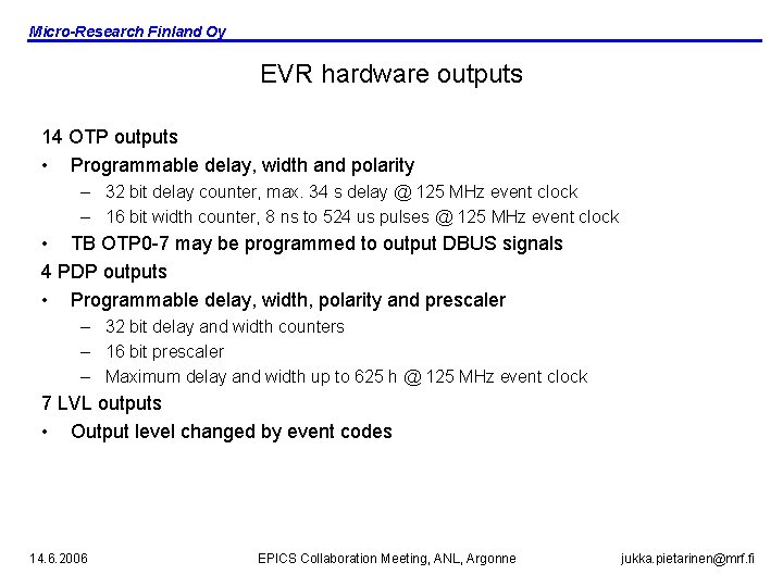
Micro-Research Finland Oy EVR hardware outputs 14 OTP outputs • Programmable delay, width and polarity – 32 bit delay counter, max. 34 s delay @ 125 MHz event clock – 16 bit width counter, 8 ns to 524 us pulses @ 125 MHz event clock • TB OTP 0 -7 may be programmed to output DBUS signals 4 PDP outputs • Programmable delay, width, polarity and prescaler – 32 bit delay and width counters – 16 bit prescaler – Maximum delay and width up to 625 h @ 125 MHz event clock 7 LVL outputs • Output level changed by event codes 14. 6. 2006 EPICS Collaboration Meeting, ANL, Argonne jukka. pietarinen@mrf. fi
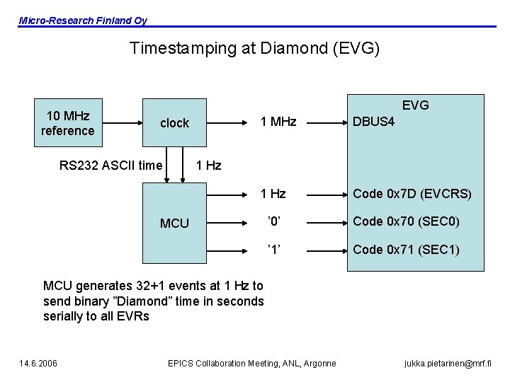
Micro-Research Finland Oy Timestamping at Diamond (EVG) 10 MHz reference EVG clock RS 232 ASCII time 1 MHz DBUS 4 1 Hz Code 0 x 7 D (EVCRS) 1 Hz MCU ’ 0’ Code 0 x 70 (SEC 0) ’ 1’ Code 0 x 71 (SEC 1) MCU generates 32+1 events at 1 Hz to send binary ”Diamond” time in seconds serially to all EVRs 14. 6. 2006 EPICS Collaboration Meeting, ANL, Argonne jukka. pietarinen@mrf. fi
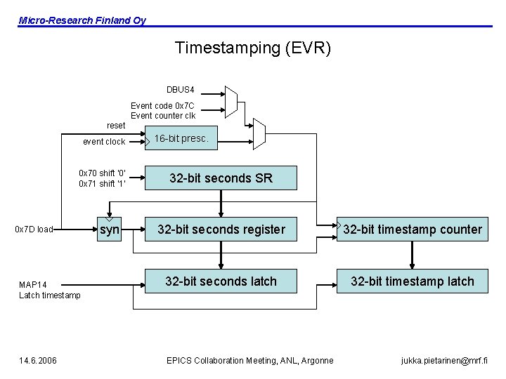
Micro-Research Finland Oy Timestamping (EVR) DBUS 4 Event code 0 x 7 C Event counter clk reset event clock 0 x 70 shift ’ 0’ 0 x 71 shift ’ 1’ 0 x 7 D load MAP 14 Latch timestamp 14. 6. 2006 syn 16 -bit presc. 32 -bit seconds SR 32 -bit seconds register 32 -bit timestamp counter 32 -bit seconds latch 32 -bit timestamp latch EPICS Collaboration Meeting, ANL, Argonne jukka. pietarinen@mrf. fi
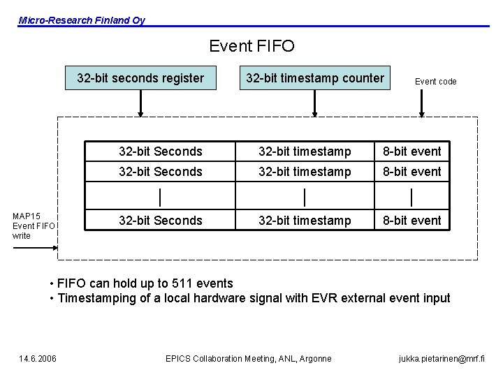
Micro-Research Finland Oy Event FIFO 32 -bit seconds register MAP 15 Event FIFO write 32 -bit timestamp counter Event code 32 -bit Seconds 32 -bit timestamp 8 -bit event | | | 32 -bit Seconds 32 -bit timestamp 8 -bit event • FIFO can hold up to 511 events • Timestamping of a local hardware signal with EVR external event input 14. 6. 2006 EPICS Collaboration Meeting, ANL, Argonne jukka. pietarinen@mrf. fi
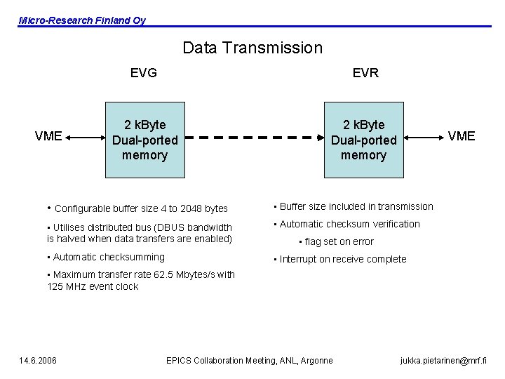
Micro-Research Finland Oy Data Transmission VME EVG EVR 2 k. Byte Dual-ported memory VME • Configurable buffer size 4 to 2048 bytes • Buffer size included in transmission • Utilises distributed bus (DBUS bandwidth is halved when data transfers are enabled) • Automatic checksum verification • Automatic checksumming • Interrupt on receive complete • flag set on error • Maximum transfer rate 62. 5 Mbytes/s with 125 MHz event clock 14. 6. 2006 EPICS Collaboration Meeting, ANL, Argonne jukka. pietarinen@mrf. fi
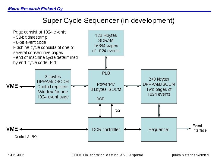
Micro-Research Finland Oy Super Cycle Sequencer (in development) Page consist of 1024 events • 32 -bit timestamp • 8 -bit event code Machine cycle consists of one or several consecutive pages • end of machine cycle determined by end-cycle code 0 x 7 f VME 8 kbytes DPRAM/DSOCM Control registers Window for one 1024 event page 128 Mbytes SDRAM 16384 pages of 1024 events PLB Power. PC 8 kbytes ISOCM 2+8 kbytes DPRAM/DSOCM Two pages of 1024 events DCR IRQ VME DCR controller Sequencer Event interface Control & IRQ 14. 6. 2006 EPICS Collaboration Meeting, ANL, Argonne jukka. pietarinen@mrf. fi
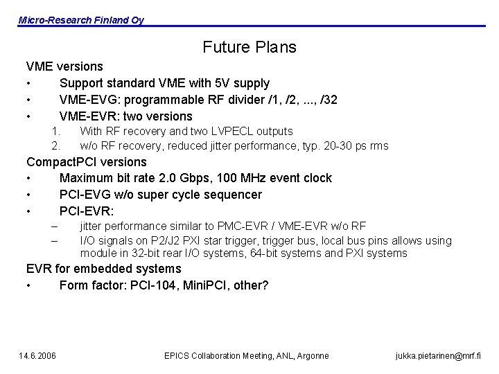
Micro-Research Finland Oy Future Plans VME versions • Support standard VME with 5 V supply • VME-EVG: programmable RF divider /1, /2, . . . , /32 • VME-EVR: two versions 1. 2. With RF recovery and two LVPECL outputs w/o RF recovery, reduced jitter performance, typ. 20 -30 ps rms Compact. PCI versions • Maximum bit rate 2. 0 Gbps, 100 MHz event clock • PCI-EVG w/o super cycle sequencer • PCI-EVR: – – jitter performance similar to PMC-EVR / VME-EVR w/o RF I/O signals on P 2/J 2 PXI star trigger, trigger bus, local bus pins allows using module in 32 -bit rear I/O systems, 64 -bit systems and PXI systems EVR for embedded systems • Form factor: PCI-104, Mini. PCI, other? 14. 6. 2006 EPICS Collaboration Meeting, ANL, Argonne jukka. pietarinen@mrf. fi
Micro-Research Finland Oy Acknowledgements • Developers of the APS timing system • Timo Korhonen, Paul Scherrer-Instute/SLS for initiating the redesign and inventing valuable features • Yuri Chernousko and Angelos Gonias from Diamond for many ideas improving the functionality • Users and evaluators of the timing system for feedback and helping to understand the requirements of various timing systems 14. 6. 2006 EPICS Collaboration Meeting, ANL, Argonne jukka. pietarinen@mrf. fi