LED Characteristics Energy of emitted photon not simply


- Slides: 12
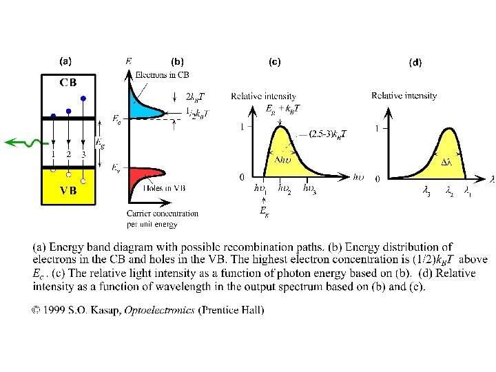
LED Characteristics • Energy of emitted photon not simply equal to the bandgap energy because electrons and holes are distributed in the CB and VB – next figure • Electron concentration is given by g(E)f(E) – g(E) is density of states and f(E) is the Fermi-Dirac function (probability of finding and electron in a state with energy E) • Asymmetrical concentration with peak at (1/2)k. BT above Ec with energy spread ~2 k. BT • Recall that the rate of recombination is proportional to both the electron and hole concentrations at the energies involved – relate figure (b) and (c) • By using =c/v we can get (d) from (c) • The linewidth of the output spectrum is defined as the width between half-intensity points as in (c) and (d)
• The wavelength and linewidth are obviously related to the energy distribution of electrons and holes density of states individual semiconductor properties • Photon energy for the peak emission is roughly Eg+k. BT (peak-to -peak transitions) • The linewidth is typically between 2. 5 k. BT to 3 k. BT • The output spectrum depends not only to the semiconductor material but also on the structure of the pn junction including the dopant concentration levels • The spectrum in (d) represents and idealized spectrum without including the effects of heavy doping on the energy bands • For a heavily doped n-type semiconductor there are so many donors that the electron wavefunctions at these donors overlap to generate a narrow impurity band centered at Ed but extending into the CB • Thus donor impurity band overlaps the CB and hence effectively lowers Ec
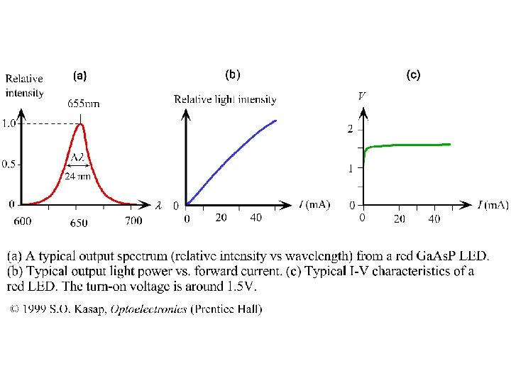
• The minimum emitted photon energy from a heavily doped semiconductors is therefore less than Eg and depends on the amount of doping spectrum change from asymmetric to more symmetric • Typical LED characteristics are shown in the next figure • More symmetric spectrum with width of 24 nm ~ 2. 7 k. BT • As LED current increases, so does the injected minority carrier concentration, thus the rate of recombination and hence the output light intensity • However the increase is not linear, at high current levels, strong injection of minority carriers leads to the recombination time depending on the injected carrier concentration and hence the current itself • Turn-on or the cut-in voltage is about 1. 5 V – current increases sharply with voltage – depends on the semiconductor and generally increases with energy bandgap • Blue – 3. 5 -4. 5 V, yellow – 2 V and infrared – 1 V
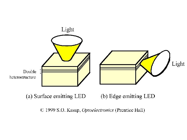
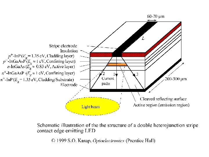
LEDs for optical communications • Type of light source suitable for optical communications depends not only on the communication distance but also on the bandwidth requirement • Short haul applications, e. g. LAN, LEDs are preferred as they are simper to drive, more economic, have a longer lifetime and provide the necessary output power even though have a wider spectrum compared to laser diode • For long haul and wide bandwidth communications laser diodes are invariably used because of their narrow linewidth, high output power and higher signal bandwidth capability • Two types of LED devices – Surface emitting LED (SLED) – emitted radiation emerges from an area in the plane of recombination layer – Edge emitting LED (ELED) – emitted radiation emerges from an area on an edge of the crystal, i. e. perpendicular to the active layer
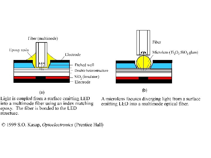
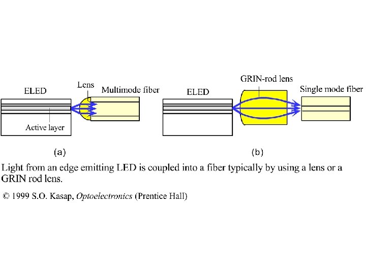
• The simplest method of coupling radiation from a SLED is to etch a well in the planar LED structure and lower the fiber as close as possible to the active region – Burrus type device • Epoxy resin is used to bond the fiber and provide index matching between glass fiber and LED material • Another method is to use a truncated spherical lens ( a microlens) with a high refractive index (n=1. 9 – 2) to focus the light into the fiber – index matching cement is used to hold them together • ELED provide greater intensity light and also more collimated light • Light guided to the edge by dielectric waveguide form by double heterostructure • Lens system is used to couple the emitted radiation from ELED to fiber • Graded index (GRIN) rod lens is used to focus light into fiber – especially single mode fiber
• Output spectra from SLED and ELED using the same material is not necessarily the same • First reason is active layers have different doping levels • Second, there is self-absorption of some of the photons guided along the active layers as in ELED • Typically ELED has narrower linewidth than SLED – In. Ga. As ELED at 1300 nm has linewidth of 75 nm where as corresponding SLED has linewidth of 125 nm