Interconnect and Packaging Lecture 3 Skin Effect ChungKuan

- Slides: 16
Interconnect and Packaging Lecture 3: Skin Effect Chung-Kuan Cheng UC San Diego 1
Outlines I. III. IV. Transmission Line Model Spectrum of Configurations Skin Effect Coaxial Cable 2
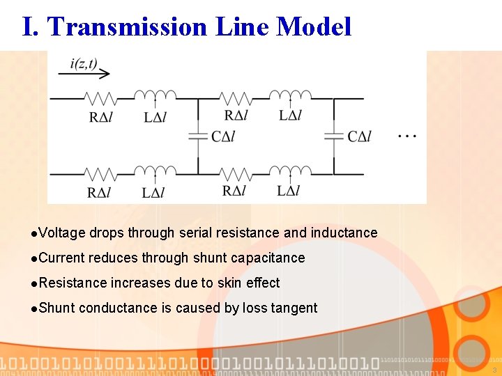
I. Transmission Line Model l. Voltage drops through serial resistance and inductance l. Current reduces through shunt capacitance l. Resistance l. Shunt increases due to skin effect conductance is caused by loss tangent 3
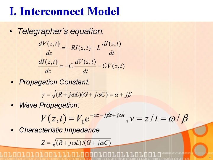
I. Interconnect Model • Telegrapher’s equation: • Propagation Constant: • Wave Propagation: • Characteristic Impedance 4
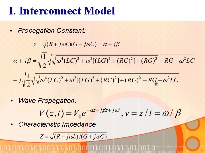
I. Interconnect Model • Propagation Constant: • Wave Propagation: • Characteristic Impedance 5
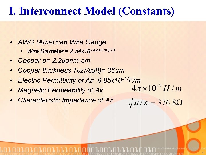
I. Interconnect Model (Constants) • AWG (American Wire Gauge • Wire Diameter = 2. 54 x 10 -(AWG+10)/20 • • • Copper p= 2. 2 uohm-cm Copper thickness 1 oz(/sqft)= 36 um Electric Permittivity of Air 8. 85 x 10 -12 F/m Magnetic Permeability of Air Characteristic Impedance of Air 6
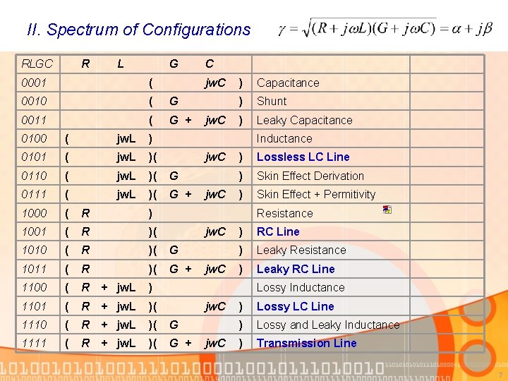
II. Spectrum of Configurations RLGC R L G 0001 ( 0010 ( G 0011 ( G + C jw. C 0100 ( jw. L ) 0101 ( jw. L )( 0110 ( jw. L )( G 0111 ( jw. L )( G + 1000 ( R ) 1001 ( R )( 1010 ( R )( G 1011 ( R )( G + 1100 ( R + jw. L ) 1101 ( R + jw. L )( 1110 ( R + jw. L )( G 1111 ( R + jw. L )( G + jw. C ) Capacitance ) Shunt ) Leaky Capacitance Inductance jw. C ) Lossless LC Line ) Skin Effect Derivation ) Skin Effect + Permitivity Resistance jw. C ) RC Line ) Leaky Resistance ) Leaky RC Line Lossy Inductance jw. C ) Lossy LC Line ) Lossy and Leaky Inductance ) Transmission Line 7
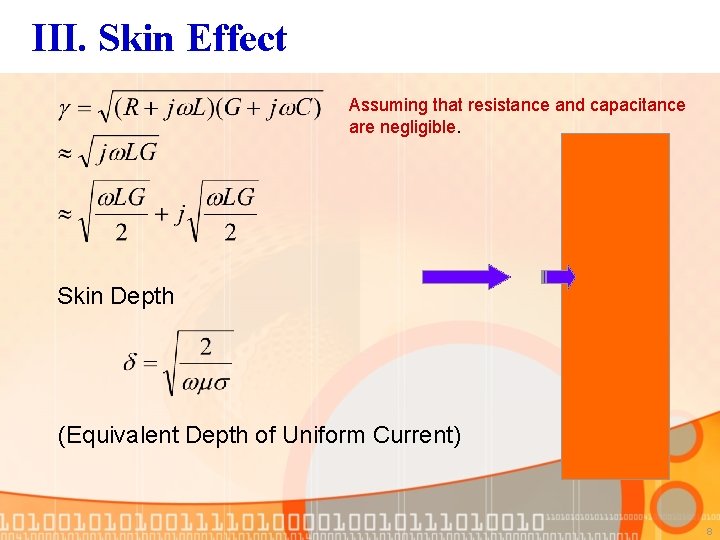
III. Skin Effect Assuming that resistance and capacitance are negligible. Skin Depth (Equivalent Depth of Uniform Current) 8
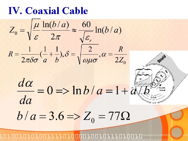
IV. Coaxial Cable 9
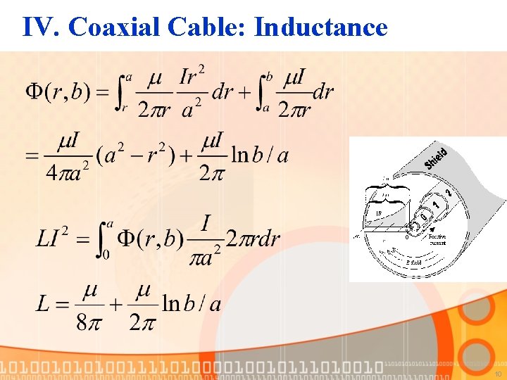
IV. Coaxial Cable: Inductance 10
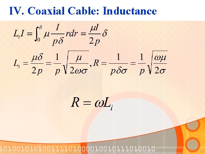
IV. Coaxial Cable: Inductance 11
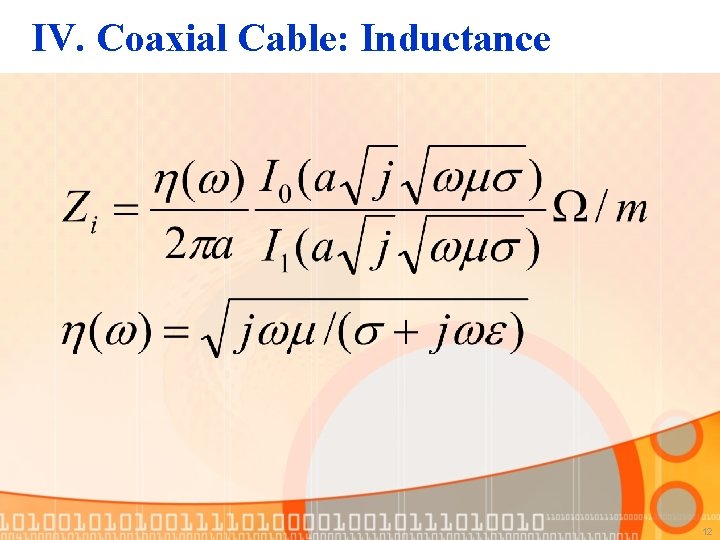
IV. Coaxial Cable: Inductance 12
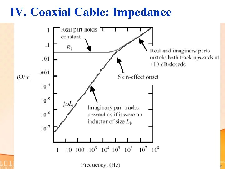
IV. Coaxial Cable: Impedance 13
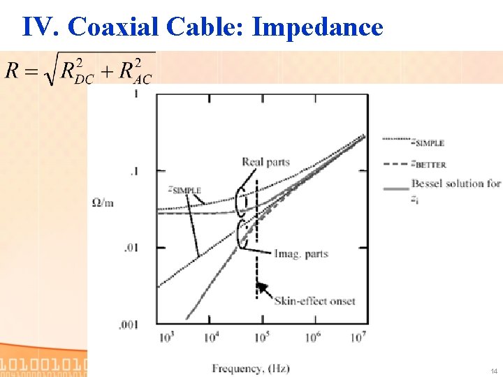
IV. Coaxial Cable: Impedance 14
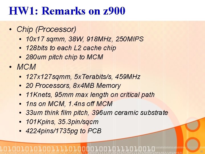
HW 1: Remarks on z 900 • Chip (Processor) • 10 x 17 sqmm, 38 W, 918 MHz, 250 MIPS • 128 bits to each L 2 cache chip • 280 um pitch chip to MCM • MCM • • 127 x 127 sqmm, 5 x. Terabits/s, 459 MHz 20 Processors, 8 x 4 MB Memory 11 Knets, 95 mm max length on critical path 1 ns on MCM, 1. 4 ns off MCM 33 um think film pitch, 396 um ceramic substrate 101 Kpins, 35. 3 pin/sqcm 4224 pins/1735 pg to PCB 15
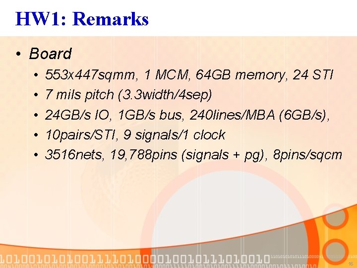
HW 1: Remarks • Board • • • 553 x 447 sqmm, 1 MCM, 64 GB memory, 24 STI 7 mils pitch (3. 3 width/4 sep) 24 GB/s IO, 1 GB/s bus, 240 lines/MBA (6 GB/s), 10 pairs/STI, 9 signals/1 clock 3516 nets, 19, 788 pins (signals + pg), 8 pins/sqcm 16