Industrial and Social Applications of Wireless Sensor Nets


 Peak Acceleration (m/s 2) Kitchen Blender")


 Procedure • 3 people ran on the stairs for")
")
")


- Slides: 20
Industrial and Social Applications of Wireless Sensor Nets with “Energy Scavenging” With a case study on “batteryless” tiny-temperature nodes for “smart building applications” Paul Wright, Jan Rabaey, David Culler, Eli Leland, Elaine Lai, Sue Mellers, Michael Montero, Jessy Baker, Brian Otis, Rob Scewczyk, and Shad Roundy (now at The Australian National University)
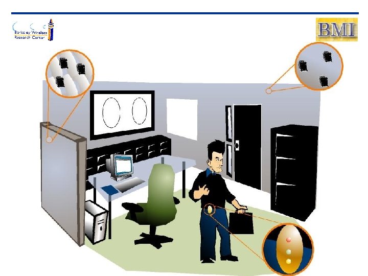
Energy Scavenging GOAL: Design an ‘infinite life’ power source for a sensor node APPLICATION: Wireless Sensor Networks in Buildings VISION: Millions of self-powered sensor/transceivers, each the size of a speck of dust, will infiltrate a building and create a smart environment PROOF OF CONCEPT: To power a Mica 2 Dot Mote using vibrations from a wooden stairway in the Naval Architecture Building
Battery, Solar, and Vibrational Energy
Common Sources of Vibrations Frequency of Peak (Hz) Peak Acceleration (m/s 2) Kitchen Blender Casing 121 6. 4 Clothes Dryer 121 3. 5 Door Frame (just after door closes) 125 3 Small Microwave Oven 121 2. 25 HVAC Vents in Office Building 60 0. 2 -1. 5 Wooden Deck with People Walking 385 1. 3 Bread Maker 121 1. 03 External Windows (size 2 ftx 3 ft) next to a Busy Street 100 0. 7 Notebook Computer while CD is Being Read 75 0. 6 Washing Machine 109 0. 5 Second Story of Wood Frame Office Building 100 0. 2 Refrigerator 240 0. 1 Vibration Source
The Piezoelectric Effect • Constitutive Equations Usable Modes of PZT 33 Mode 3 2 1 d = strain s = stress Y = Young’s modulus d = piezoelectric coeff. D = electrical displacement e = dielectric constant E = electric field + V - 31 Mode 3 2 1 + V - F
Tungsten proof mass, glued base, PZT bender Pirelli Piezoelectric Device Staircase Piezoelectric device
Piezoelectric Bimorph Generators Piezoelectric generator C Load Vs Rs
Wooden Stairs Peak Frequency at 26. 8 Hz FFT of frequencies Power generator must match peak frequency of vibration source for max power output Vibrations from walking down stairs
Bender Design Characteristics • Piezoelectric: PZT • Tungsten Alloy Mass: 52 g • Beam Dimensions: 1. 25” x 0. 02” Behavior 40 V peak–to-peak output from bender when someone walks down the stairs • Resonant Frequency: 26. 8 Hz • Power Output: 450 μW
Tiny Temp Storage Capacitor Power Circuit Mote Piezoelectric Power Generator Thermistor
Power Circuit Voltage Out to Mote Voltage In from Bender Rectifier Voltage Regulator Piezo Bender CST 6600μF Enable Regulator ~ VIN Rectifier Comparator (3. 5 V – 5 V) Comparator Storage Capacitor Vout = 3. 3 V DC
Load Requirements • Mica 2 Dot Mote • 3. 3 Input Voltage • 800 ms ‘Startup Time’ • 45 m. W to take temperature reading and transmit information
FDM Packaging Upper Case Temperature Sensor Hole Capacitor Holders PCB Holder Bridge Bender Platform Lower Case Tabs
Proof of Concept #1 (CEC) Procedure • 3 people ran on the stairs for 40 minutes Capacitor Discharging 5 V 3. 5 V Results 816 ms Power Out • 3. 28 V for 816 ms • 2 temperature readings transmitted
Proof of Concept #2 (Fire)
Proof of Concept #2 (Fire)
Next Steps: Short Term Charge Up Time Mica 2 dot mote Pico. Radio-based node Efficiency
Next Steps: Long Term Design a variable resonant frequency MEMS bender which adapts to vibration sources with different peak frequencies. Inertial Mass Cantilever Beam Substrate TMSM PDMS Si. O 2 Si PZT Platinum Si 3 N 4 Aluminum Si. O 2 Si Flip and Bond Assembly
Many Thanks! • Thanks to CITRIS, NSF & the California Energy Commission for their sponsorship