Experience 1 RF characterization of an Aluminum model


- Slides: 9

Experience #1: RF characterization of an Aluminum model of the ELI-NP S-band RF-Gun

RF photocathode electron Gun Main Electron sources: • Thermionic cathode Ø Electrons generated by thermionic emission klystron • Photo-electric cathode Ø Ø Ø Electrons are generated by photoelectric effect. Very short pulse laser (picosecond) strikes a metallic photocathode, which is embedded in an electromagnetic accelerating structure. SW structure composed by two RF cavities The emitted bunch of electrons is trapped and accelerated in the device Employ fast laser pulses to produce bunchtrains. Picosecond bunches can be formed at the RF repetition rate, easing the following electron-bunching structure system The ratio of the number of electrons emitted per incident photon is called Quantum Efficiency (Qe) which is a function of the photon energy. For metals, the minimum-energy photons are typically in the ultraviolet range (λ(Cu) < 267 nm). Master Oscillator RF signal Drive Laser Solenoid Electron beam

ELI-NP Linac RF electron Gun 1. 6 cell photoinjector of the BNL/SLAC/UCLA type with new features: • elliptical shaped irises with larger aperture • Symmetric port to compensate the dipole field component • coupling hole rounded to reduce the pulsed heating • cooled cathode • fabrication without brazing using the clamping gasket technique RF frequency GHz 2. 856 Rep. Rate Hz 100 Working Mode π mode (SW) Max Rf input power MW 16 RF peak field at the cathode MV/m 120 Average dissipated power k. W 1. 5 Unloaded Q factor 14500 Coupling coefficent β 3 Working temperature °C 33 34 Filling time ns 420 Shunt Impedance MΩ/m 1. 64 Type of cathode copper waveguide Beam tube pumping port cathode

ELI-NP RF electron Gun Prototype Two cavities coupled together -> Two resonant modes The π mode is used as accelerating mode Main Parameters π-mode 0 -mode Input waveguide Mode frequency cathode Freq. separation Input coupling coeff. (ß) Full cell Beam pipe QL Q 0 R/Q factor - Filling time - ½ cell Vacuum tube

Slater theorem For a cavity on resonance, the electric and magnetic stored energies are equal. If a small perturbation is made on the cavity wall, this will generally produce an imbalance of the electric and magnetic energies, and the resonant frequency will shift to restore the balance. The Slater perturbation theorem describes the shift of the resonant frequency, when a small volume ΔV is removed from the cavity of volume V. The general result is Where U is the total stored energy. This theorem can be used also to measure the field profiles in the cavity by inserting a perturbing object and measuring the frequency shifts while moving it along selected paths. The theorem mathematical expression is different in this case and form factors need to be introduced because field lines are strongly deformed in this case, while they are almost unperturbed when the boundary is slightly deformed.

Bead Drop Measurement If the perturbing object (bead) is a perfectly conducting sphere the values of the form factors are: If a sphere of radius a is moved along the beam axis of a cavity the E field profile and the R/Q of a resonant accelerating mode can be estimated according to: Sign of the E-field profile Nylon wire Network Analyzer Probe bead

1. RF Gun characterization in reflection with Network Analizer q Localize the two resonating modes (no calibration needed) measuring the S 11 in reflection with a big span (100 MHz). q Estimate the frequency separation between the two modes. (Why is it important? ) q Measure the frequency and the coupling factor ß for the two modes (calibration needed) 2. RF Gun characterization in transmission with Network Analizer q Measure the S 21 of the device and using the «Bandwidth» function (Marker Search -> Bandwidth) measure the Loaded Quality Factor QL q Calculate the Unloaded Quality Factor Q 0 3. Longitudinal electric field profile measurement with “bead-drop” technique (mode π): q Ticks drawn on the Nylon wire are equally spaced every 5 mm q Fill an excel spreadsheet with 2 columns: bead position (z) and measured fres (use your laptop) q Calculate and plot ∆f/f vs z;

4. Accelerating voltage and R/Q calculation: q From the same spreadsheet, calculate Vacc and then R/Q q The spherical bead radius is 0. 0018 m, ε=8. 85418781762 E-12, c=299792458 5. Filling time measurement (time domain with realistic RF pulse) q The filling time, is the time for the energy stored in the cavity with loaded Q = QL to build to 1/e of its saturation point q Connect the RF signal generator through a switch and an amplifier to the Gun and read the output probe through the oscilloscope 100 Hz, few us pulses 5 V switch fπ scope q Measure the filling time τ of the gun. Compare it with the one evaluated from QL 6. Longitudinal electric field profile measurement with “bead-drop” technique (mode 0) q Repeat the procedure of point 3 for the 0 mode

Useful Formulae and definitions Perturbation measurements:
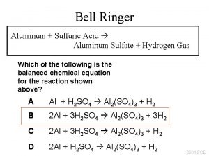
 Aluminum + sulfuric acid = aluminum sulfate + hydrogen
 Imprint definition psychology
 Early experience vs later experience
 Example of indirect experience
 In direct characterization
 Indirect and direct characterization
 Drawing bohr diagrams
 Electron cloud diagram
 Aluminum and iron iii oxide balanced equation
 Aluminum family
