DIESEL CYCLE DIESEL CYCLE Diesel cycle is very


= V")

- Slides: 11
DIESEL CYCLE
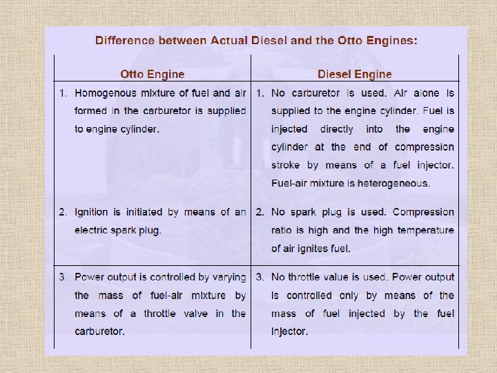
DIESEL CYCLE Diesel cycle is very similar to Otto cycle, most of diesel engines used in many applications such as: four stroke type engine, we usually use the diesel engine in the heavy load like trucks and buses. Diesel cycle is an application on internal combustion engines where the explosion happens by the pressure not by the spark (Otto cycle).
Diesel cycle Operations Intake Stroke The intake stroke in a Diesel engine is used to draw in a new volume of charge air into the cylinder. As the power generated in an engine is dependent on the quantity of fuel burnt during combustion and that in turn is determined by the volume of air (oxygen) present, most diesel engines use turbochargers to force air into the cylinder during the induction stroke. From a theoretical perspective, each of the strokes in the cycle complete at Top Dead Centre (TDC) or Bottom Dead Centre (BDC), but in practicality, in order to overcome mechanical valve delays and the inertia of the new charge air, and to take advantage of the momentum of the exhaust gases.
Diesel cycle Operations Compression Stroke The compression stroke begins as the inlet valve closes and the piston is driven upwards in the cylinder bore by the momentum of the crankshaft and flywheel. The purpose of the compression stroke in a Diesel engine is to raise the temperature of the charge air to the point where fuel injected into the cylinder spontaneously ignites. In this cycle, the separation of fuel from the charge air eliminates problems with auto-ignition and therefore allows Diesel engines to operate at much higher compression ratios than those currently in production with the Otto Cycle.
Diesel cycle Operations Compression Ignition Compression ignition takes place when the fuel from the high pressure fuel injector spontaneously ignites in the cylinder. In theoretical cycle, fuel is injected at TDC, but as there is a finite time for the fuel to ignite (ignition lag) in practical engines, fuel is injected into the cylinder before the piston reaches TDC to ensure that maximum power can be achieved. This is synonymous with automatic spark ignition advance used in Otto cycle engines.
Diesel cycle Operations Power Stroke The power stroke begins as the injected fuel spontaneously ignites with the air in the cylinder. As the rapidly burning mixture attempts to expand within the cylinder walls, it generates a high pressure which forces the piston down the cylinder bore. The linear motion of the piston is converted into rotary motion through the crankshaft. The rotational energy is imparted as momentum to the flywheel which not only provides power for the end use, but also overcomes the work of compression and mechanical losses incurred in the cycle (valve opening and closing, alternator, fuel injector pump, water pump, etc. ).
Diesel cycle Operations Exhaust Stroke The exhaust stroke is as critical to the smooth and efficient operation of the engine as that of induction. As the name suggests, it's the stroke during which the gases formed during combustion are ejected from the cylinder. This needs to be as complete a process as possible, as any remaining gases displace an equivalent volume of the new charge air and leads to a reduction in the maximum possible power.
Diesel cycle diagrams • Process 1 -2: Reversible adiabatic Compression. • Process 2 -3: Constant pressure heat addition. • Process 3 -5: Reversible adiabatic Compression. • Process 4 -1: Constant volume heat rejection.
Diesel cycle Where g = Cp / Cv Cut of ratio (rc )= V 3 / V 2
The end