FUEL cycle in diesel engine The Diesel Engine


 Low cetane")


 Store fuel Prevent pressure fluctuations")
 • Responsible for maintaining the pressure in the rail at a")


 diesel engine,")

 High-pressure common rail Roger")

 Roger Krieger, GM R&D Center")
 – diesel fuel The advantages of electronic unit injection are")


 Digital electronics allow both sensors and actuators to be monitored.")
- Slides: 44
FUEL cycle in diesel engine
The Diesel Engine “. . an internal combustion engine in which air is compressed to a temperature sufficiently high to ignite fuel injected into the cylinder where the combustion actuates a piston. ” Roger Krieger, GM R&D Center
Diesel Fuel If you have ever compared diesel fuel and gasoline, you know that they are different. They certainly smell different. Diesel fuel is heavier and oilier. Diesel fuel evaporates much more slowly than gasoline -- its boiling point is actually higher than the boiling point of water. You will often hear diesel fuel referred to as "diesel oil" because it is so oily.
Diesel VS Gazoline Diesel fuel evaporates more slowly because it is heavier. It contains more carbon atoms in longer chains than gasoline does (gasoline is typically C 9 H 20, while diesel fuel is typically C 14 H 30). It takes less refining to create diesel fuel, which is why it is generally cheaper than gasoline.
DIESEL FUEL Diesel fuel must meet an entirely different set of standards than gasoline. The fuel in a diesel engine is not ignited with a spark, but is ignited by the heat generated by high compression. All diesel fuel must be clean, be able to flow at low temperatures, and be of the proper cetane rating. Cleanliness. Low-temperature fluidity. Cetane number.
Diesel Fuel Characteristics Cetane number Measure of relative ease to initiate combustion Higher number: easier to ignite Octane number for gas: opposite Higher number: less tendency to ignite
Cetane Number Ignition quality measure Affects: cold starting, warm-up, combustion roughness, acceleration, and exhaust smoke density Cetane number is based on the ignition characteristics of two hydrocarbons: Cetane - short delay period and ignites readily (100) Alphamethylnaphthalene (AMN) - long delay period and poor ignition quality (0) It is the percentage by volume of normal cetane in a blend with AMN PC engines require a minimum cetane no. of 35 DI engines require a minimum cetane no. of 40
Cetane Number High cetane number indicates good ignition quality (short delay period) Low cetane number indicates poor ignition quality (long delay period) PC engines require a minimum cetane # of 35 DI engines require a minimum cetane # of 40 Cetane improver additive can improve ignition quality and reduce white smoke during start up
DIESEL FUEL Injection system Types • • • In-line pump system The distributor pump system Common rail system The unit injector fuel system Electronic Diesel Control
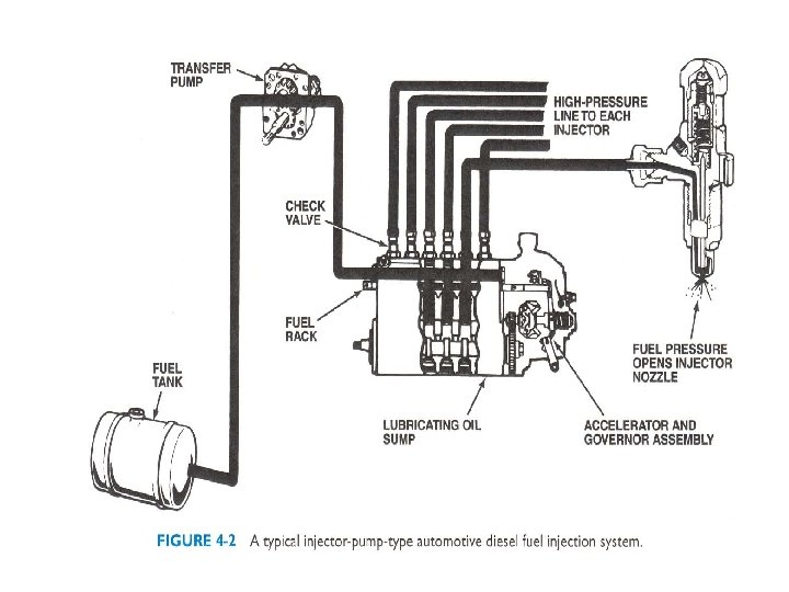
In-line pump system
FUEL CYCLE
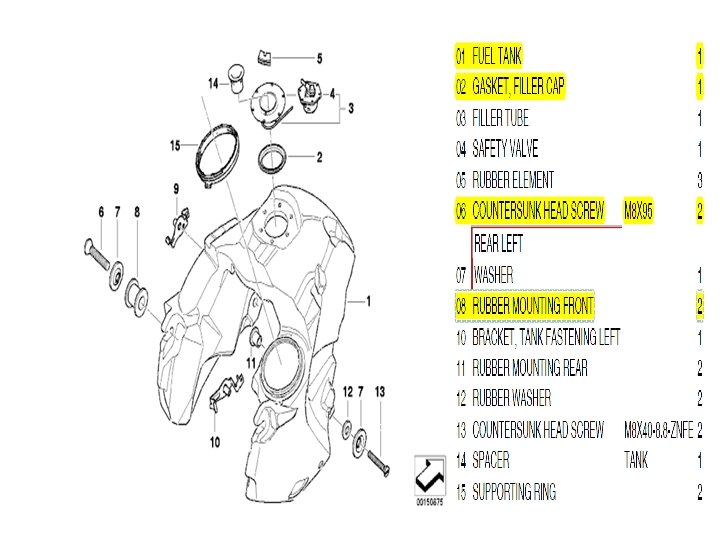
Diesel Fuel Injection system Components • Fuel tank • Fuel lines • Filters WInjection nozzles
Diesel Fuel Injection system Components • Injection nozzles
Glow Plugs for Indirect Injection
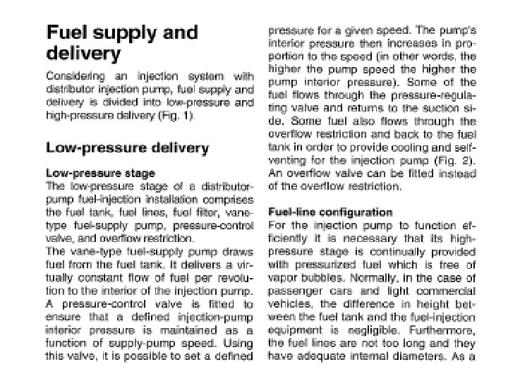
Diesel Fuel Injection system Components • • Supply pump Plunger pump Gear pump Vane pump
FUEL FILTERS The fuel filtration and water separation needs of today's new generation diesel fuel systems demand extremely high efficiency, flexibility, multiple functions and ease of use with no risk of fuel spills or contaminated parts. Stan dyne's patented Fuel Manager® range of Available for light, medium and heavy duty trucks; and agricultural, industrial, construction and marine applications, there is a Fuel Manager
The FM 1000 Series is designed for diesel engines with a fuel flow rate up to 180 US gallons/hr (680 liters/hr). Typical engines range from 200 to
Fuel pump The ‘traditional’ style of injection pump is the in-line pump. They have been used for many decades and are still commonly found on agricultural and stationary diesels, and very many older model diesel road vehicles still employ them, including the Toyota Land cruiser 2 H diesel. . They are typically capable of generating injection nozzle pressures up to about 750 bar in light road vehicles – towards the lower end of the range that is required these days.
They have a separate pump plunger for each cylinder of the engine, so a 4 cylinder engine has a four plunger pump, a 6 cylinder engine has a six plunger pump, etc. The pump is run at half engine crankshaft speed and has a central shaft with four/six etc. cam lobes attached. Each plunger is operated by it’s cam once every two crankshaft revolutions, coinciding of course with the power stroke of its engine cylinder. • Each plunger has a spiral groove or helix machined on it’s side and cut through to the top of the plunger. • When operated, the plunger is pushed up by its cam lobe. • At a certain point the spiral groove will line up with a spill port on the side of the plunger cylinder and the rest of the fuel is ‘spilled’.
So that all engine cylinders receive the same sized fuel charge, all of the plungers are rotated together. This is achieved by each plunger having gear teeth machined to it’s circumference which are engaged by a common gear rack which runs through the pump body. As the rack moves back and forth, all four (or six or more) plungers are rotated together. The extremes of travel of the pump rack control the minimum and maximum fuel charge quantities the pump is capable of
PRE SUPPLY PUMP The electric fuel pump comprises of: 1. Electric Motor 2. Roller-Cell Pump 3. Non Return Valve
PRE SUPPLY PUMP • The roller cell is driven by an electric motor. • Its rotor is mounted eccentrically and provided with slots in which movable rollers are free to travel. The rollers are forced against the base plate by rotation and by fuel pressure. The fuel is transported to the outlet openings on the pump’s pressure side.
PRE SUPPLY PUMP variants • Gear type fuel pump ï The drive gear wheel is driven by the engine. ï Delivery quantity is directly proportional to engine speed. ï Shut off is by means of an electromagnet. .
High- pressure accumulator (Rail) Store fuel Prevent pressure fluctuations
Pressure-control valve (DRV) • Responsible for maintaining the pressure in the rail at a constant level.
Fuel Injector The injector on a diesel engine is its most complex component and has been the subject of a great deal of experimentation -- in any particular engine it may be located in a variety of places. The injector has to be able to withstand the temperature and pressure inside the cylinder and still deliver the fuel in a fine mist.
pre-combustion chambers Getting the mist circulated in the cylinder so that it is evenly distributed is also a problem, so some diesel engines employ special induction valves, pre-combustion chambers or other devices to swirl the air in the combustion chamber or otherwise improve the ignition and combustion process.
DIESEL ENGINES Indirect and Direct Injection A direct injection diesel engine injects the fuel directly into the combustion chamber. Many designs do not use a glow plug.
DIESEL ENGINES Indirect and Direct Injection In an indirect injection (abbreviated IDI) diesel engine, fuel is injected into a small prechamber, which is connected to the cylinder by a narrow opening. The initial combustion takes place in this prechamber. This has the effect of slowing the rate of combustion, which tends to reduce noise. An indirect injection diesel engine uses a prechamber and a glow plug.
DIESEL ENGINES Diesel Fuel Ignition • Ignition occurs in a diesel engine by injecting fuel into the air charge, which has been heated by compression to a temperature greater than the ignition point of the fuel or about 1, 000°F (538°C).
Fuel Injection Systems Electronic distributor pump Electronic unit injector (EUI) High-pressure common rail Roger Krieger, GM R&D Center
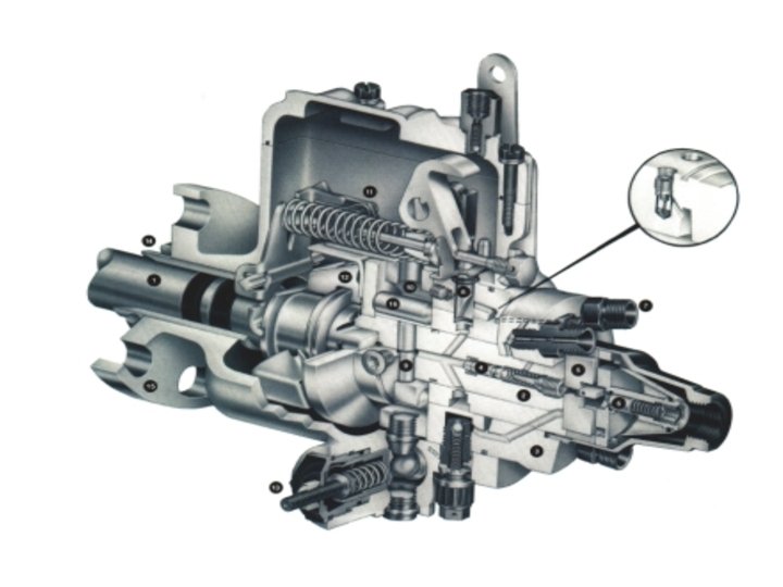
Electronic Distributor Pump
Electronic Unit Injector (EUI) Roger Krieger, GM R&D Center
Electronic unit injection (EUI) – diesel fuel The advantages of electronic unit injection are as follows. Lower emissions Electronic fuel quantity and timing control provides a very quick transient response, improving vehicle drivability. Control of all engine functions Electronically controlled pilot injection also reduces combustion noise. Communication with other systems Linked to the ECU, the EUI system can communicate with other vehicle systems such as ABS, transmission and steering, making further systems In the EUI system, the fuel injection pump, the injector and a solenoid valve are combined in one, single unit; these unit injectors are located in the cylinder-head, above the combustion chamber. The EUI is driven by a rocker arm, which is in turn driven by the engine camshaft.
High-Pressure Common Rail Spill Control Valve Injectors Fuel Return to Tank ECU High-Pressure Pump
High-Pressure Common Rail
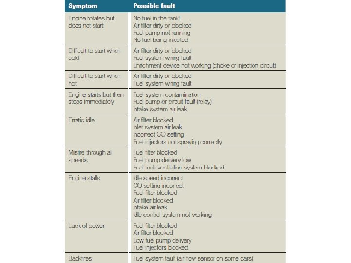
Diagnosing fuel control system faults As with all systems, the six stages of fault-finding should be followed. 1. Verify the fault. 2. Collect further information. 3. Evaluate the evidence. 4. Carry out further tests in a logical sequence. 5. Rectify the problem. 6. Check all systems. Note that when diagnosing engine fuel system faults, the same symptoms may indicate an ignition problem.
The following procedure is generic and, with a little adaptation, can be applied to any fuel injection system. 1. Check battery state of charge (at least 70%). 2. Hand eye checks (all fuel and electrical connections secure and clean). 3. Check fuel pressure supplied to rail (in multipoint systems it will be about 2. 5 bar but check specifications). 4. If the pressure is not correct jump to stage 10. 5. Is injector operation OK? – continue if not (suitable spray pattern or dwell reading across injector supply). 6. Check supply circuits from main relay (battery volts minimum). 7. Continuity of injector wiring (0– 0. 2Ω) and note that many injectors are connected in parallel). 8. Sensor readings and continuity of wiring (0– 0. 2Ω for the wiring sensors will vary with type). 9. If no fuel is being injected and all tests so far are OK, suspect ECU. 10. Fuel supply – from stage 4. 11. Supply voltage to pump. 12. Check pump relay and circuit (note in most cases the ECU closes the relay but this may be bypassed on cranking). 13. Ensure all connections (electrical and fuel) are remade correctly.
On-board diagnostics (OBD) Digital electronics allow both sensors and actuators to be monitored.