cg w rof niag qerf wol hgi H

 Gp(s) From specs: => desired Bode shape of Gol(s)")


![n=[1]; d=[1/5/50 1/5+1/50 1 0]; figure(1); clf; margin(n, d); %proportional control design: figure(1); hold](https://slidetodoc.com/presentation_image_h2/68f1d2dcc4cd87be4867d00e3388c7b5/image-10.jpg "n=[1]; d=[1/5/50 1/5+1/50 1 0]; figure(1); clf; margin(n, d); %proportional control design: figure(1); hold")


![n=[1]; d=[1/5/50 1/5+1/50 1 0]; figure(1); clf; margin(n, d); hold on; grid; V=axis; Mp](https://slidetodoc.com/presentation_image_h2/68f1d2dcc4cd87be4867d00e3388c7b5/image-14.jpg "n=[1]; d=[1/5/50 1/5+1/50 1 0]; figure(1); clf; margin(n, d); hold on; grid; V=axis; Mp")


![clear all; n=[1]; d=[1/5/50 1/5+1/50 1 0]; figure(1); clf; margin(n, d); grid; V=axis; hold](https://slidetodoc.com/presentation_image_h2/68f1d2dcc4cd87be4867d00e3388c7b5/image-17.jpg "clear all; n=[1]; d=[1/5/50 1/5+1/50 1 0]; figure(1); clf; margin(n, d); grid; V=axis; hold")


![n=[1]; d=[1 5 0 0]; figure(1); clf; margin(n, d); grid; hold on; Mp=16; PMd](https://slidetodoc.com/presentation_image_h2/68f1d2dcc4cd87be4867d00e3388c7b5/image-23.jpg "n=[1]; d=[1 5 0 0]; figure(1); clf; margin(n, d); grid; hold on; Mp=16; PMd")


/dgc(end-2); ess=1; Kad=1/ess; zlag = w_gcd/20; plag = zlag/(Kad/Kaa); ngcc = conv(ngc,")


- Slides: 33
cg w rof niag qerf wol hgi. H rof niag qerf hgih wo. L raen MP tneiciffu. S gw Desired Bode plot shape
Controller design with Bode C(s) Gp(s) From specs: => desired Bode shape of Gol(s) Make Bode plot of Gp(s) Add C(s) to change Bode shape Get closed loop system Run step response, or sinusoidal response
Overall Loop shaping strategy • Overall gain K to select wgc – By shifting gain plot up and down • PD or lead to add more PM @ wgc – Both PD and lead has positive phase • PI or lag to increase low freq gain – But both has negative phase, – deteriorates PM • Low pass filter to reduce high freq gain – For noise attenuation – Also has negative effect on PM
Lag Controller Design
z/p=40 z/p=20 Desired effect: low freq gain boost for improved steady state tracking z/p=10 z/p=5 z=wgcd/5 wgcd Kill PM by 10 to 12 deg
z/p=40 z/p=20 Desired effect: low freq gain boost for improved steady state tracking z/p=10 z/p=5 z=wgcd/10 wgcd Kill PM by 5 to 7 deg
z/p=40 z/p=20 z/p=10 z/p=5 Want these: DC gain boosting z=wgcd/20 wgcd Don’t want these: PM reduction! Kill PM by 2 to 3 deg
Lag and lead-lag Design Steps • From plant, draw Bode plot • From specs => PMd and wgcd – If there is speed or BW req, wgcd, • In this case, if PM not enough, design PD or lead – Otherwise, choose wgcd to have PM>PMd • • • Find K to enforce wgcd: Find Kp, v, a-have with K and C above Find Kp, v, a-des from ess specs zlag/plag = Kp, v, a-des/Kp, v, a-have Let zlag= wgcd/10~20, depending on PM room Compute plag
Lag design example • Plant transfer function is given by: • Desired design specifications are: – Step response overshoot <= 10% – Steady state tracking error to ramp input is <=0. 01 Note: no speed or BW requirement, so just choose wgcd to have enough PM
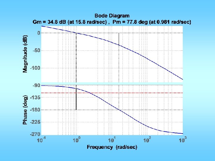
n=[1]; d=[1/5/50 1/5+1/50 1 0]; figure(1); clf; margin(n, d); %proportional control design: figure(1); hold on; grid; V=axis; Mp = 10; PMd = 70 – Mp + 3; semilogx(V(1: 2), [PMd-180], ': r'); %get desired w_gc x=ginput(1); w_gcd = x(1); K = 1/abs(evalfr(tf(n, d), j*w_gcd)); Kva = K*n(end)/d(end-1); ess=0. 01; Kvd=1/ess; z = w_gcd/5; p = z/(Kvd/Kva); ngc = conv(n, Kp*[1 z]); dgc = conv(d, [1 p]); figure(1); hold on; margin(ngc, dgc); [ncl, dcl]=feedback(ngc, dgc, 1, 1); figure(2); step(ncl, dcl); grid; figure(3); margin(ncl*1. 414, dcl); grid;
Designed for 63 Lag killed 12
Overshoot too much
n=[1]; d=[1/5/50 1/5+1/50 1 0]; figure(1); clf; margin(n, d); hold on; grid; V=axis; Mp = 10; PMd = 70 – Mp + 3; semilogx(V(1: 2), [PMd-180], ': r'); x=ginput(1); w_gcd = x(1); %get desired w_gc K = 1/abs(polyval(n, j*w_gcd)/polyval(d, j*w_gcd)); Kva = K*n(end)/d(end-1); ess=0. 01; Kvd=1/ess; z = w_gcd/10; p = z/(Kvd/Kva); ngc = conv(n, K*[1 z]); dgc = conv(d, [1 p]); figure(1); hold on; margin(ngc, dgc); [ncl, dcl]=feedback(ngc, dgc, 1, 1); figure(2); step(ncl, dcl); grid; figure(3); margin(ncl*1. 414, dcl); grid;
clear all; n=[1]; d=[1/5/50 1/5+1/50 1 0]; figure(1); clf; margin(n, d); grid; V=axis; hold on; Mp = 10; PMd = 70 – Mp + 7; semilogx(V(1: 2), [PMd-180], ': r'); x=ginput(1); w_gcd = x(1); %get desired w_gc K = 1/abs(polyval(n, j*w_gcd)/polyval(d, j*w_gcd)); Kva = K*n(end)/d(end-1); ess=0. 01; Kvd=1/ess; z = w_gcd/10; p = z/(Kvd/Kva); ngc = conv(n, K*[1 z]); dgc = conv(d, [1 p]); figure(1); hold on; margin(ngc, dgc); [ncl, dcl]=feedback(ngc, dgc, 1, 1); figure(2); step(ncl, dcl); grid; figure(3); margin(ncl*1. 414, dcl); grid;
Lead-Lag design example • Plant transfer function is given by: • Desired design specifications are: – Step response overshoot <= 16% – Step response rise time <= 2 sec – Steady state tracking error to unit acceleration input is <=1 Note: we have all three types of specs: speed, relative stability, and tracking
Strategy • First do a lead design to fix speed and overshoot requirement • Then do a lag design to fix the ess.
n=[1]; d=[1 5 0 0]; figure(1); clf; margin(n, d); grid; hold on; Mp=16; PMd = 70 – Mp + 1; tr = 2; wn = 1. 8/tr; w_gcd = wn*0. 8; PM = pi+angle(evalfr(tf(n, d), j*w_gcd)); phimax = PMd*pi/180 -PM; alpha=(1+sin(phimax))/(1 -sin(phimax)); zlead=w_gcd/sqrt(alpha); plead=w_gcd*sqrt(alpha); K=sqrt(alpha)/(abs(evalfr(tf(n, d), j*w_gcd))); ngc = conv(n, K*[1 zlead]); dgc = conv(d, [1 plead]); figure(1); margin(ngc, dgc); [ncl, dcl]=feedback(ngc, dgc, 1, 1); figure(2); step(ncl, dcl); grid; figure(3); margin(ncl*1. 414, dcl); grid;
Need to reduce by Mp by 10% So increase PMd by 10 deg
Overshoot is too large. Plus, we know the lag controller will further deteriorate Mp. So, redesign for better Mp.
About 12% overshoot. So, let’s go ahead with lag design.
Kaa = ngc(end)/dgc(end-2); ess=1; Kad=1/ess; zlag = w_gcd/20; plag = zlag/(Kad/Kaa); ngcc = conv(ngc, [1 zlag]); dgcc = conv(dgc, [1 plag]); figure(1); margin(ngcc, dgcc); [ncl, dcl]=feedback(ngcc, dgcc, 1, 1); figure(4); step(ncl, dcl); grid; figure(5); margin(ncl*1. 414, dcl); grid; We don’t have too much room to spare for Mp, so choose 20 so that the lag controller only kills about 3 degrees of PM, which will add about 3 percentage points to Mp.