Aerodynamics Preliminary Design Review 2 Phoenix Aerospace Aerodynamics


- Slides: 23

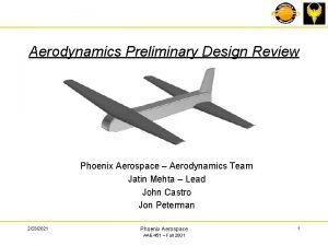
Aerodynamics Preliminary Design Review #2 Phoenix Aerospace – Aerodynamics Team Jatin Mehta – Lead Jon Peterman John Castro 1/23/2022 Phoenix Aerospace AAE 451 – Fall 2001 1

Objectives Recalculate aerodynamic values from PDR #1 Finalize wing & aircraft parameters - Wing shape - - Span Taper Sweep Dihedral Twist Incidence Wing separation Vertical Tail Size Fuselage shape - Length Cross section Updated Lift and Drag Coefficients Aircraft three view 1/23/2022 Phoenix Aerospace AAE 451 – Fall 2001 2

Concept Review 1. Tandem wing concept 1. Chosen initially for theoretical drag reduction 1. “a short-coupled, high canard has some desirable characteristics. ” SAE paper, Feistel et. Al 2. Further analysis shows that drag reduction is small 1. Drag reduction due to vertical separation 2. Actual reduction may be hard to achieve - Concept retained for multiple reasons - Worst case: drag equal to single wing case - Amount of analysis completed - Allows for compact wings with no break in each wing 1/23/2022 Phoenix Aerospace AAE 451 – Fall 2001 3

Airfoil selection process revised - L 3/2/D compared for multiple airfoils Cdmin compared for all airfoils Manufacturability compared - Max thickness - Trailing edge shape 1/23/2022 Phoenix Aerospace AAE 451 – Fall 2001 4

Airfoil selection - Cdmin = 0. 0138 Selig S 1210 chosen for both wings Trailing edge manufacturing is no longer a concern due to manufacturing tests 1/23/2022 Phoenix Aerospace AAE 451 – Fall 2001 5

Wing Sizing Process - Area ratio (Sfront: Srear) - Determined by equal lift requirement - 15% Clrear degradation factor due to downwash - Equal spans - Result from industry paper (wind tunnel testing) - Taper & sweep - Taper used to approximate elliptical loading - Sweep not required for low speed flight - Resulting wing shapes evaluated - Greater front wing AR to promote early front wing stall - Manufacturability (airfoil thickness & tip chord) - Twist & incidence - Twist determined to prevent tip-stall - CMARC used to determine incidence angle of wings 1/23/2022 Phoenix Aerospace AAE 451 – Fall 2001 6

Wing Sizing Area Ratio - Equal lift provides lowest induced drag - Dynamic pressure, q, equal for both wings Downwash from front wing degrades CL of rear wing 15% Degradation factor assumed for rear wing CL (representative of calculated values) Total wing area from constraint analysis and weight predictions, Stot = 8. 83 ft 2 - With Cltotal and Stotal known, Sfront & Srear can be solved 1/23/2022 Phoenix Aerospace AAE 451 – Fall 2001 7

Wing Sizing - Theoretical induced drag reduction can be seen Theory assumes no interaction between front and rear wings 1/23/2022 Phoenix Aerospace AAE 451 – Fall 2001 8

Wing Sizing Equal Spans - Wind tunnel test performed by Feistel et. al, determined that tandem wings of equal spans had the best benefit With front and rear wing areas known setting equal spans sets the aspect ratio To meet size requirements for ease of transport b = 6 ft - Taper & Sweep - No sweep required for slow flight Optimum taper ratio for elliptical lift distribution, l = 0. 3 l = 0. 6, for producible tip chord With spans, areas, & taper ratio known wing shape is determined Twist, dihedral, & Incidence - Twist used to prevent tip stall (Raymer guidelines) Front twist = -1 o Rear twist = -2 o 3 o used for preliminary dihedral, will be updated for stability PDR Incidence set using CMARC model of wings Incidence: Front = 4 o Rear = 4 o 1/23/2022 Phoenix Aerospace AAE 451 – Fall 2001 9

Wing Sizing Upper pressure distribution very similar for both wings 1/23/2022 Phoenix Aerospace AAE 451 – Fall 2001 10

Wing Sizing Lower pressure distribution similar for both wings 1/23/2022 Phoenix Aerospace AAE 451 – Fall 2001 11

Wing Sizing Wing Separation - Horizontal separation has minimal effect on aerodynamics - Any changes due to horizontal spacing can be negated by taper, twist, & incidence - Horizontal separation (. 25 C to. 25 C) = 3 ft - Vertical separation has effect on induced drag - Maximum separation gives most induced drag benefit - Separation limited by drag & weight - Vertical separation = 6 in 1/23/2022 Phoenix Aerospace AAE 451 – Fall 2001 12

Vertical Tail Sizing Vertical Tail - Vertical tail size estimated using stability derivatives - Cnb is primary stability derivative for tail sizing - Cnb must be greater than 0. 057 1/rad - Vertical tail will be finalized with Stability & Control PDR Vertical tail area = 1 ft 2 1/23/2022 Phoenix Aerospace AAE 451 – Fall 2001 13

Fuselage Sizing Fuselage - Fuselage sized to meet vertical and horizontal separations Size will be updated to meet Structural needs Fuselage length = 54. 9 in Maximum fuselage width = 5 in Maximum fuselage height = 6 in 1/23/2022 Phoenix Aerospace AAE 451 – Fall 2001 14

Three View of Aircraft 1/23/2022 Phoenix Aerospace AAE 451 – Fall 2001 15

Coefficients & Conclusions Lift & Drag Coefficients - Design aircraft CL = 0. 55 CD =. 0106 CD calculated using drag code - Drag number is low, Code must be examined Conclusions - Aerodynamic work near completion All numbers must be examined and revised - Drag code must be thoroughly examined 1/23/2022 Phoenix Aerospace AAE 451 – Fall 2001 16

Appendix 1/23/2022 Phoenix Aerospace AAE 451 – Fall 2001 17

Appendix 1/23/2022 Phoenix Aerospace AAE 451 – Fall 2001 18

Appendix 1/23/2022 Phoenix Aerospace AAE 451 – Fall 2001 19

Appendix Front wing wake for cruise conditions Front wing wake for a=-3 o 1/23/2022 Phoenix Aerospace AAE 451 – Fall 2001 20

Appendix Front wing wake for a=-4. 5 o 1/23/2022 Phoenix Aerospace AAE 451 – Fall 2001 21

Appendix Front wing tip flowfield (cruise condition) 1/23/2022 Phoenix Aerospace AAE 451 – Fall 2001 22

Appendix Rear wing tip flowfield (cruise condition) 1/23/2022 Phoenix Aerospace AAE 451 – Fall 2001 23
 Honeywell aerospace deer valley
 Preliminary design review example
 Pdr preliminary design review
 Preliminary design review example
 Preliminary review definition
 Aerospace design process
 Aerospace systems design and simulation
 Fins for rockets
 Aerodynamics of rockets
 Aerodynamic dragster
 China aerodynamics research and development center
 Basic
Basic Aerodynamics
 Define aerodynamics
 Force of air resistance formula
 Uiuc applied aerodynamics group
 Air and aerodynamics
 Aerodynamics of race cars
 Forward cg vs aft cg
 Aerodynamics system identification key
 Induced drag formula
 Aae 520
 Preliminary budget
 Preliminary treatment adalah
