The SPS 800 MHz RF system E Shaposhnikova
- Slides: 18
The SPS 800 MHz RF system E. Shaposhnikova for BE/RF LIU-SPS Coordination meeting 4 April 2012 Acknowledgments: T. Argyropoulos, T. Bohl, T. Linnecar, E. Montesinos
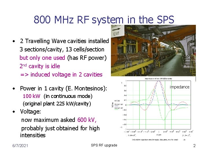
800 MHz RF system in the SPS • 2 Travelling Wave cavities installed 3 sections/cavity, 13 cells/section but only one used (has RF power) 2 nd cavity is idle => induced voltage in 2 cavities • Power in 1 cavity (E. Montesinos): impedance 100 k. W (in continuous mode) (original plant 225 k. W/cavity) • Voltage: now maximum asked 600 k. V, probably just obtained for high intensities 6/7/2021 SPS RF upgrade 2
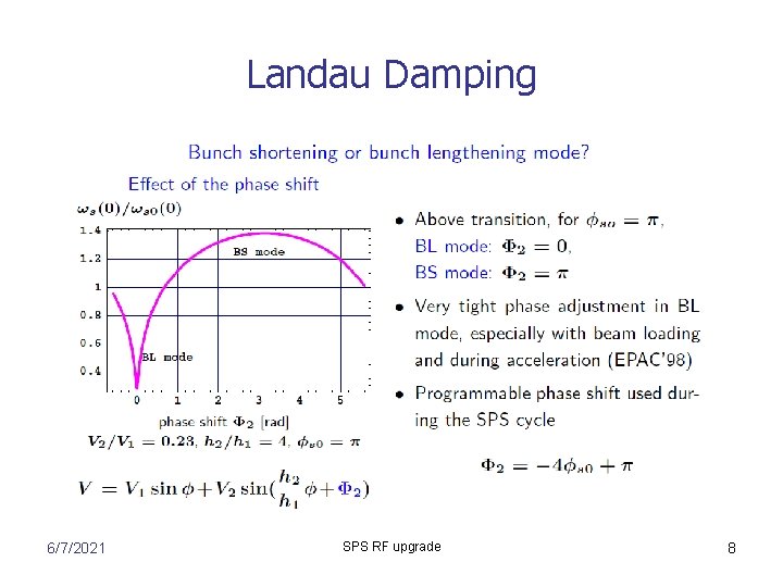
800 MHz RF system in the SPS • Is required for beam stability above bunch intensity of (2 -3)x 1010 • It is used for all LHC beams from injection to extraction in bunch shortening mode • Its phase is locked to the 200 MHz voltage, but the relative phase should be programmed during the cycle (according to the stable phase). Absolute phase is calibrated at the start of each run from beam measurements (bunch tilt at injection and beam stability during the cycle) • It is essential but not sufficient for beam stability above nominal intensities and controlled longitudinal emittance blow-up is applied using band limited noise. It should be inside synchrotron frequency distribution which depends on the voltage and phase of the 800 MHz RF system affected by beam loading 6/7/2021 SPS RF upgrade 3
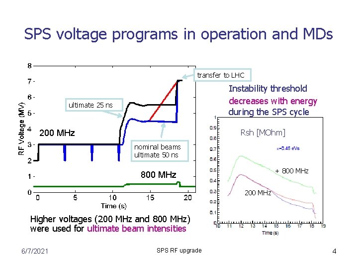
SPS voltage programs in operation and MDs transfer to LHC Instability threshold decreases with energy during the SPS cycle ultimate 25 ns Rsh [MOhm] 200 MHz nominal beams ultimate 50 ns + 800 MHz 200 MHz Higher voltages (200 MHz and 800 MHz) were used for ultimate beam intensities 6/7/2021 SPS RF upgrade 4
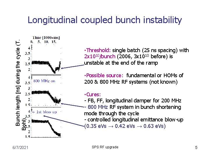
Bunch length [ns] during the cycle (T. Bohl) Longitudinal coupled bunch instability 6/7/2021 • Threshold: single batch (25 ns spacing) with 2 x 10¹⁰/bunch (2006, 3 x 10¹⁰ before) is unstable at the end of the ramp • Possible source: fundamental or HOMs of 200 & 800 MHz RF systems (not known) • Cures: - FB, FF, longitudinal damper for 200 MHz - 800 MHz RF system in bunch shortening mode through the cycle - controlled longitudinal emittance blow-up (0. 35 e. Vs → 0. 42 e. Vs → 0. 63 e. Vs) SPS RF upgrade 5
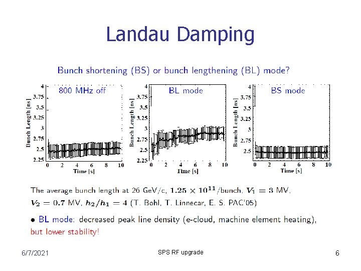
Landau Damping 6/7/2021 SPS RF upgrade 6
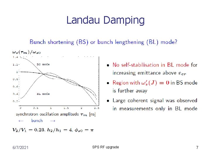
Landau Damping 6/7/2021 SPS RF upgrade 7
Landau Damping 6/7/2021 SPS RF upgrade 8
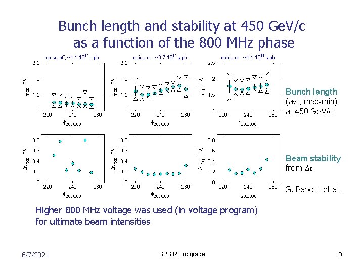
Bunch length and stability at 450 Ge. V/c as a function of the 800 MHz phase Bunch length (av. , max-min) at 450 Ge. V/c Beam stability from ∆τ G. Papotti et al. Higher 800 MHz voltage was used (in voltage program) for ultimate beam intensities 6/7/2021 SPS RF upgrade 9
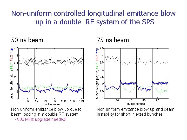
Non-uniform controlled longitudinal emittance blow -up in a double RF system of the SPS 50 ns beam 75 ns beam • ni Non-uniform emittance blow-up due to beam loading in a double RF system => 800 MHz upgrade needed! Non-uniform emittance blow-up and beam instability for short injected bunches
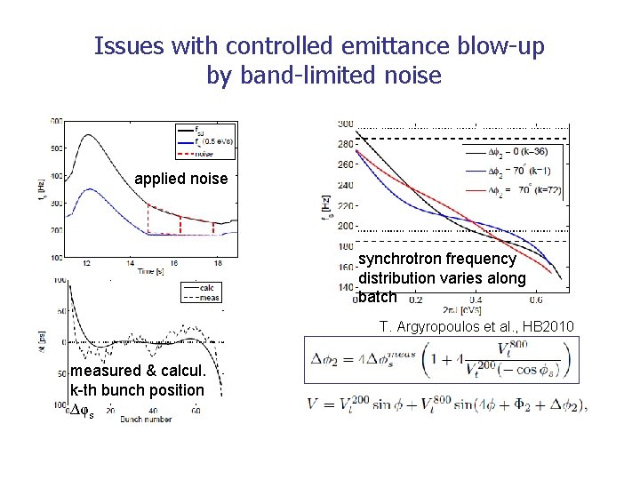
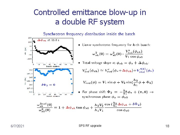
Issues with controlled emittance blow-up by band-limited noise applied noise synchrotron frequency distribution varies along batch T. Argyropoulos et al. , HB 2010 measured & calcul. k-th bunch position ∆φs
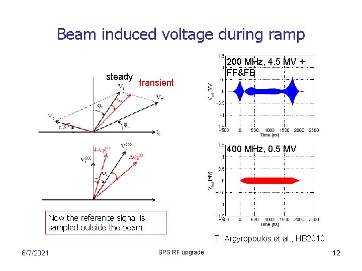
Beam induced voltage during ramp steady 200 MHz, 4. 5 MV + FF&FB transient 400 MHz, 0. 5 MV Now the reference signal is sampled outside the beam T. Argyropoulos et al. , HB 2010 6/7/2021 SPS RF upgrade 12
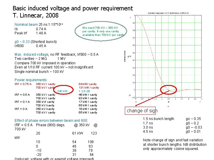
Basic induced voltage and power requirement T. Linnecar, 2008 Nominal beam 25 ns 1. 15*1011 Ib 0. 74 A Peak Irf 1. 48 A We need 700 KV – 350 KV per cavity. If only one cavity available then 700 k. V per cavity g 0 ~ 0. 33 (Shortest bunch) Irf 800 0. 45 A Max. induced voltage, no RF feedback, Irf 800 ~ 0. 5 A Two cavities ~ 2 MΩ 1 MV Compare 700 k. V imposed in operation Even at 1/10 RF current 100 k. V – not insignificant Single nominal bunch ~ 100 k. V Power requirements: IRF = 0. 75 A 350 k. V / cavity 700 k. V / cavity IRF = 0. 5 A 350 k. V / cavity 700 k. V / cavity 350 k. V/ cavity 700 k. V /cavity 350 k. V /cavity 700 k. V / cavity 240 k. W IRF = 0. 1 A IRF = 0 A 84 k. W/ cavity 131 k. W / cavity + 2. 6 d. B 46 k. W / cavity 93 k. W / cavity 17 k. W / cavity 65 k. W / cavity 16 k. W / cavity 65 k. W / cavity Effect of phase errors between beam and 800: IRF = 0. 5 A Phase (800) degs. @ 350 k. V @ 700 k. V 20 61 KW 123 k. W 10 54 109 0 46 93 -10 38 78 -20 31 64 change of sign 1. 5 ns bunch length 1. 7 ns 3. 0 ns 4. 5 ns go ~ 0. 35 g 0 ~ 0. 2 g 0 ~ -0. 03 g 0 ~ 0. 01 Note change of sign and fast variation at shorter bunch lengths. NB distribution only approximately cosine squared.
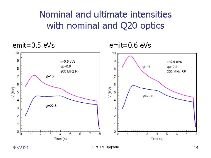
Nominal and ultimate intensities with nominal and Q 20 optics emit=0. 5 e. Vs 6/7/2021 emit=0. 6 e. Vs SPS RF upgrade 14
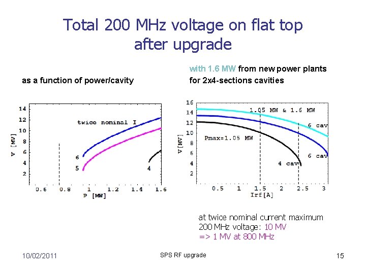
Total 200 MHz voltage on flat top after upgrade as a function of power/cavity with 1. 6 MW from new power plants for 2 x 4 -sections cavities at twice nominal current maximum 200 MHz voltage: 10 MV => 1 MV at 800 MHz 10/02/2011 SPS RF upgrade 15
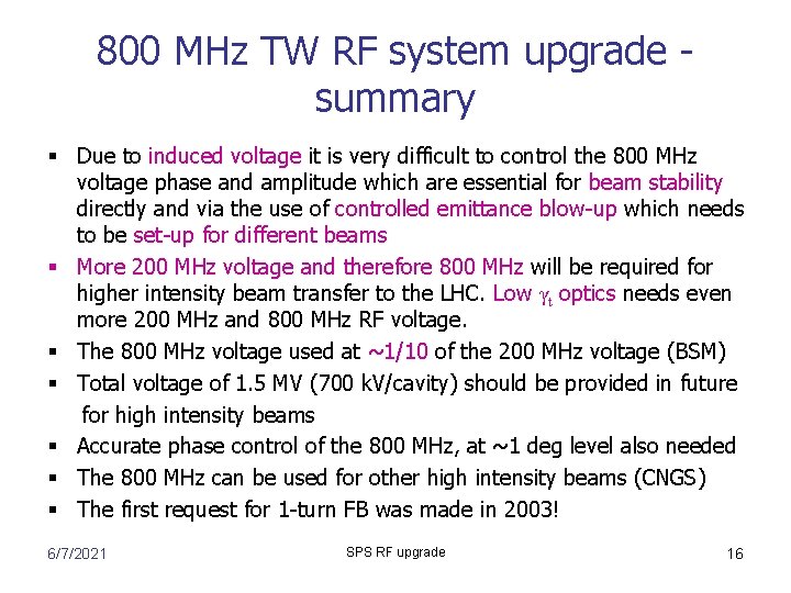
800 MHz TW RF system upgrade summary § Due to induced voltage it is very difficult to control the 800 MHz voltage phase and amplitude which are essential for beam stability directly and via the use of controlled emittance blow-up which needs to be set-up for different beams § More 200 MHz voltage and therefore 800 MHz will be required for higher intensity beam transfer to the LHC. Low γt optics needs even more 200 MHz and 800 MHz RF voltage. § The 800 MHz voltage used at ~1/10 of the 200 MHz voltage (BSM) § Total voltage of 1. 5 MV (700 k. V/cavity) should be provided in future for high intensity beams § Accurate phase control of the 800 MHz, at ~1 deg level also needed § The 800 MHz can be used for other high intensity beams (CNGS) § The first request for 1 -turn FB was made in 2003! 6/7/2021 SPS RF upgrade 16
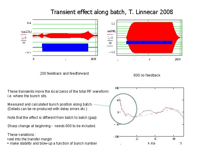
Transient effect along batch, T. Linnecar 2008 200 feedback and feedforward These transients move the local zeros of the total RF waveform i. e. where the bunch sits. Measured and calculated bunch position along batch. (Details can be re-produced with delay errors etc. ) Note that the effect is different from batch to batch (gap) Sharp change at beginning - needs 800 to be included. These variations : • eat into the transfer margin • make stability and blow-up a function of bunch number 800 no feedback
Controlled emittance blow-up in a double RF system 6/7/2021 SPS RF upgrade 18