P12463 HYDRODYNAMIC KITE MODEL DESIGN REQUIREMENTS Design and
- Slides: 1
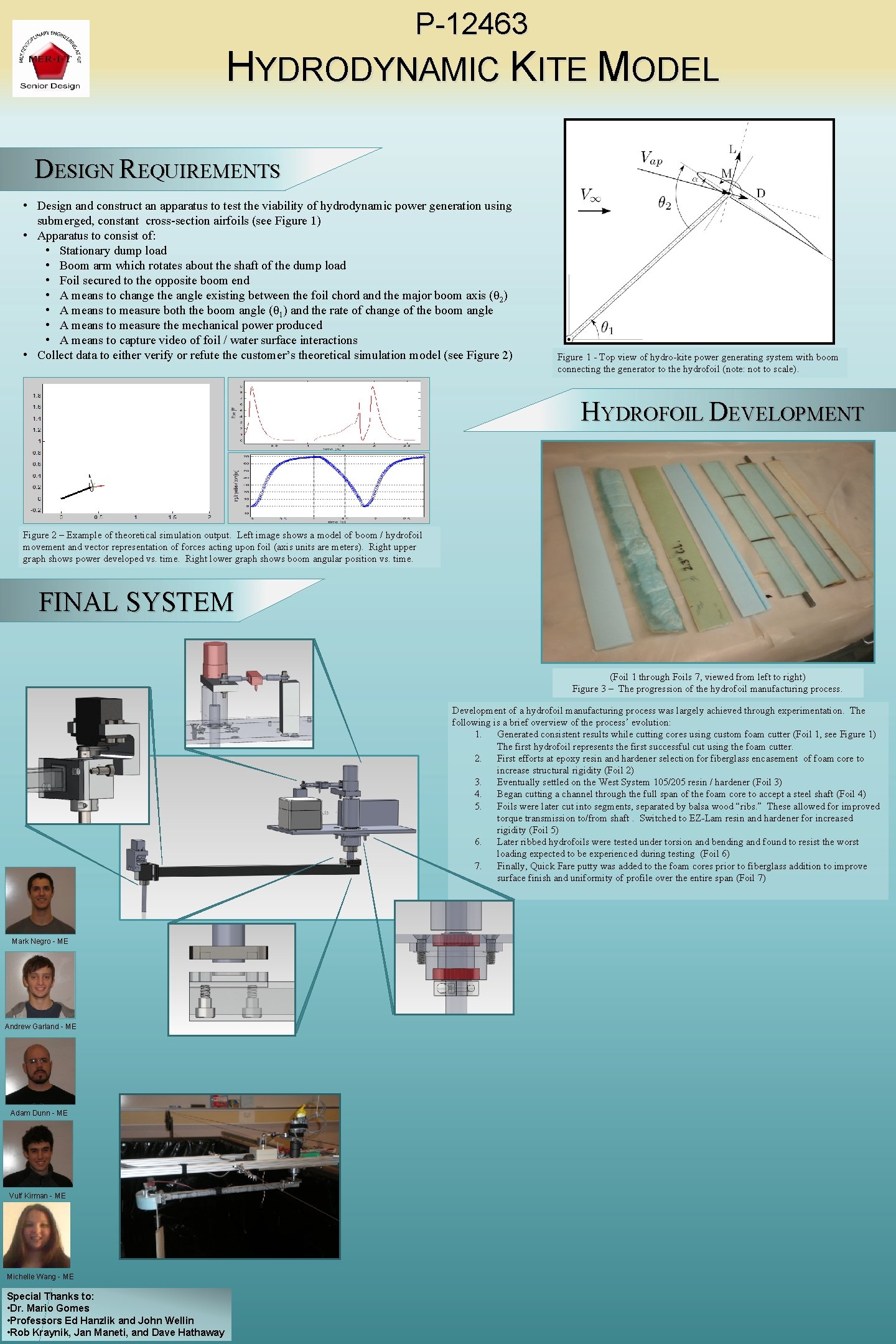
P-12463 HYDRODYNAMIC KITE MODEL DESIGN REQUIREMENTS • Design and construct an apparatus to test the viability of hydrodynamic power generation using submerged, constant cross-section airfoils (see Figure 1) • Apparatus to consist of: • Stationary dump load • Boom arm which rotates about the shaft of the dump load • Foil secured to the opposite boom end • A means to change the angle existing between the foil chord and the major boom axis (θ 2) • A means to measure both the boom angle (θ 1) and the rate of change of the boom angle • A means to measure the mechanical power produced • A means to capture video of foil / water surface interactions • Collect data to either verify or refute the customer’s theoretical simulation model (see Figure 2) Figure 1 - Top view of hydro-kite power generating system with boom connecting the generator to the hydrofoil (note: not to scale). HYDROFOIL DEVELOPMENT Figure 2 – Example of theoretical simulation output. Left image shows a model of boom / hydrofoil movement and vector representation of forces acting upon foil (axis units are meters). Right upper graph shows power developed vs. time. Right lower graph shows boom angular position vs. time. FINAL SYSTEM (Foil 1 through Foils 7, viewed from left to right) Figure 3 – The progression of the hydrofoil manufacturing process. Development of a hydrofoil manufacturing process was largely achieved through experimentation. The following is a brief overview of the process’ evolution: 1. Generated consistent results while cutting cores using custom foam cutter (Foil 1, see Figure 1) The first hydrofoil represents the first successful cut using the foam cutter. 2. First efforts at epoxy resin and hardener selection for fiberglass encasement of foam core to increase structural rigidity (Foil 2) 3. Eventually settled on the West System 105/205 resin / hardener (Foil 3) 4. Began cutting a channel through the full span of the foam core to accept a steel shaft (Foil 4) 5. Foils were later cut into segments, separated by balsa wood “ribs. ” These allowed for improved torque transmission to/from shaft. Switched to EZ-Lam resin and hardener for increased rigidity (Foil 5) 6. Later ribbed hydrofoils were tested under torsion and bending and found to resist the worst loading expected to be experienced during testing (Foil 6) 7. Finally, Quick Fare putty was added to the foam cores prior to fiberglass addition to improve surface finish and uniformity of profile over the entire span (Foil 7) Mark Negro - ME Andrew Garland - ME Adam Dunn - ME Vulf Kirman - ME Michelle Wang - ME Special Thanks to: • Dr. Mario Gomes • Professors Ed Hanzlik and John Wellin • Rob Kraynik, Jan Maneti, and Dave Hathaway