YOKOGAWA Welcome To Integrated Production Control System DCS


")
 1. HIS Requirement")


")
")

 YOKOGAWA")
")
 YOKOGAWA FCS Function")
 Logic Chart Block LC 64 Program Control")
 Sequence Table")


 Condition : 當SWN 105 -A為ON(MV=2)。 Action")
 Condition : TIC 102 -A 的 DV(Deviation, PV-SV)大於-5℃。 Action")
 Condition Action : 當TIC 102 -A 的DV(Deviation)小於 5℃。 :")
 Condition Action : TMR 114 -A 計時時間到(Reactor End Waiting")
 YOKOGAWA FCS 01 01 HIS 01 XX Control Hint : ◆ FCS Type")

- Slides: 50
YOKOGAWA Welcome To Integrated Production Control System DCS : 分 散式控制系統
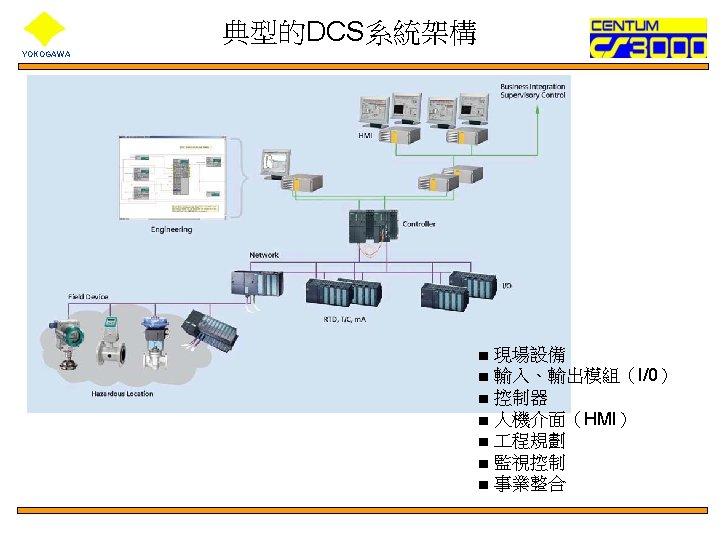
System Configuration YOKOGAWA LCD Solid Console Ethernet Desktop HIS LCD Open Console CGW HIS +Eng Function V-net Enclose Style Console HIS RFCS 2 KFCS LFCS SFCS Open Display Style Console HIS Remote I/O ooo Small FCS FF-H 1 ooo Large FCS HIS : Human Interface Station V-Net : CS 3000 Control Bus CGW : Communication Gateway Unit BCV : Bus Converter BCV new Migration type FCS Migrated FCS SFCS LFCS KFCS RFCS 2 : Compact Field Control Station : Standard Field Control Station for RIO : Standard Field Control Station for FIO : Migration Type Field Control Station
YOKOGAWA 控制器 KFCS Configuration of KFCS Cabinet
YOKOGAWA Standard Type FCS: KFCS
YOKOGAWA ANR 10 D FIO Node (Cabinet)
YOKOGAWA Part B. HIS Function ( HIS: Human Interface station ) 1. HIS Requirement & Application Capacity 2. Operating Windows 3. Test Function
HIS Requirement YOKOGAWA . CPU Pentium III 866 MHz or over . Main memory HIS: Human Interface station 128 MB or more for operation and monitoring function 256 MB or more for operation and monitoring function and builder function. Hard disk 10 GB or more (20 GB or more recommended in installing builder function). Bus slot Two PCI slot for V net interface (AIP 261 is an option interface card for Operation keyboard, and touch panel. ) (On-board 10/100 Base LAN card). Floppy disk. CD-ROM drive. Parallel port. CRT. Keyboard. Mouse port. Serial port 3. 5 inch (1. 44 MB) One or more Centronic DSUB 25 -pin x 1 (for printer) 17 inch or lager, 1024 x 768 (256 color) or more 106 keyboard PS 2 2 -button RS-232 -C x 1
Application Capacity of HIS YOKOGAWA CS 1000 CS 3000 Number of tags 8000 100, 000 Max. Windows 1000 2500 Graphic windows Displayed Process Data Modifiers Trend windows Number of pens 400 Data per Window 8 Data per Object 100 Data per Window 200 Data per window 8 Pen per Window Data Axis 1, 2, 5, 10 Time Axis 1/4, 1/2, 1, 2, 4, 8 Scan Period Recording Time Control Windows 200 Data per Window No. of Instrument Faceplate 1 sec. , 10 sec. , 1 min. , 2 min. , 5 min. , 10 min. 48 min. , 8 hours, 2 days, 4 days, 10 days, 20 days 16 per Window Trend Turning Trend Acquisition Cycle 1 sec. Reserve Function: 16 points Trend function No. of points acquired Other station Acquisition 16 points 1, 10 sec. Scan period: Max. 256 points(2 block) 1024 point, 8 block 2560 point, 20 block (Including one/ten-second trend acquisition points) Max. 1024 point, 8 block Max. 6400 points, 50 block
Operating windows I YOKOGAWA * 利用滑鼠 * * 利用操作鍵盤 * 利用滑鼠點選出現在螢幕上的 Icon. 直接按操作鍵盤上的按鍵來開啟視窗. The following functions can be assigned to the 32 function keys: u Calling of windows u Execution of system function keys u Starting, stopping or restarting of trends u Flashing or turning On/OFF of led’s u Execution of programs by their filename u Execution of the multimedia function
Operating windows II YOKOGAWA Navigator Window Control Group Window Overview Window calling up by mouse clicking
Operating windows III YOKOGAWA Custom Graphic Window Trend Point Window
Operation window: System Message YOKOGAWA System Message Area Process alarms Navigator System alarms Name entry Operator guides Toggle HIS/NT Security Clear screen Windows calls Buzzer reset Operation menu Hard copy Preset menu Date and time Latest 5 alarms Icons Main Panel area
YOKOGAWA Operation window: Navigator
Operation window: Graphic YOKOGAWA
Operation window: Overview YOKOGAWA
YOKOGAWA Operation window: Control
Operation window: Trend YOKOGAWA
Operation window: Tuning YOKOGAWA
Operation window: Faceplate 1/2 YOKOGAWA
Operation window: Faceplate 2/2 YOKOGAWA
Operation window: Process Alarm YOKOGAWA
Operation window: Sequence Table YOKOGAWA
Logic Charts YOKOGAWA
Operation window: Process Report YOKOGAWA
Operation window: Historical Message YOKOGAWA
Operation window: System Status YOKOGAWA
CS 3000 Test functions YOKOGAWA Virtual Testing Target Test HIS Function HIS Software I/O Switching Virtual Wiring IN TAG 01 OUT PID FCS Simulator I/O Simulator FCS Target test using actual FCS without actual field wiring
YOKOGAWA Part C FCS Function
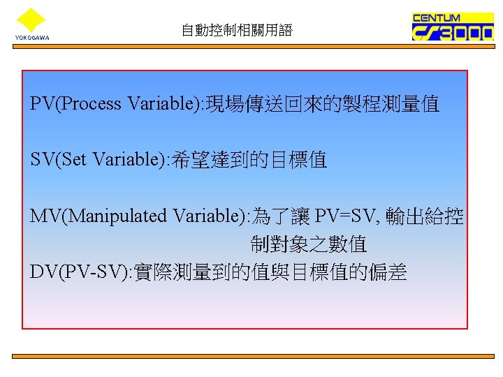
YOKOGAWA 自動控制相關用語 FEEDBACK CONTROL(回饋控制)
YOKOGAWA 自動控制相關用語 FEEDFORWARD CONTROL(前饋控制)
Structure of Regulatory Control Function YOKOGAWA PID Controller Block Terminal Connection SET Process Connection Analog Input Module I/O define IN Analog Input Module PID Controller Block out Analog Output Module
Types of the Regulatory Control Blocks (1/3) YOKOGAWA
YOKOGAWA Types of the Regulatory Control Blocks (2/3)
Types of the Regulatory Control Blocks (3/3) YOKOGAWA FCS Function
Sequence Control Function YOKOGAWA Condition Control (Monitoring) Logic Chart Block LC 64 Program Control (Phase Step) Sequence Table Block ST 16 E FCS Function SFC Block _SFCSW _SFCPB _SFCAS Switch Instrument Sequence Element Block SI-1 SI-2 SO-1 SO-2 SIO-11 SIO-12 SIO-21 SIO-22 SIO-12 P SIO-22 P TM CTS CTP CI CO RL RS
Sequence Table Block YOKOGAWA Function Block Dia. (ST 16, ST 16 E) Sequence Table Example Sequence Function
Logic Chart Block YOKOGAWA Sequence Function
Calculation Blocks YOKOGAWA FCS Function 範例
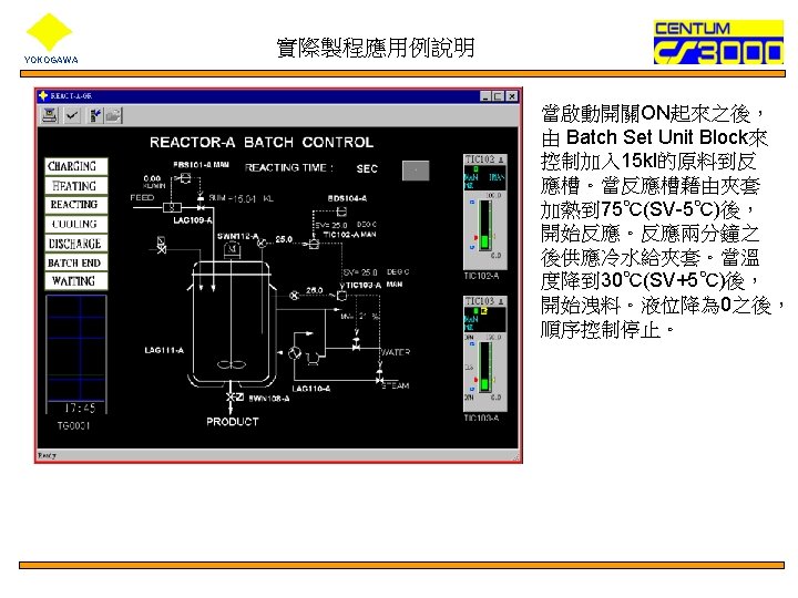
實際製程應用例說明 YOKOGAWA 批次控制的Sequence Table 內容說明 Step A 1(Charging) Condition : 當SWN 105 -A為ON(MV=2)。 Action : 將Flow Batch Set Unit 切成AUT。 觸發Operation Guide Message(%OG 0001, Reactor-A Charging)。 Step A 2(Heating) Condition : 收到由FBS 101 -A所發出的Batch Set End 的信號。 Action : 觸發Annunciator ANM 115 -A(Reactor-A charge End)。 將一次側溫度控制器TIC 102 -A的SV值設 定為 80℃。 設定TIC 102 -A 的PID參數(BDS 104 -A的 DTnn的值) 將TIC 102 -A的Block Mode 切成AUT。 將TIC 103 -A的Block Mode 切成CAS。 觸發Operation Guide Message(%OG 0002, Reactor-A Heating)
YOKOGAWA 實際製程應用例說明 Step A 3(Reacting) Condition : TIC 102 -A 的 DV(Deviation, PV-SV)大於-5℃。 Action : 啟動計算反應時間的Timer TMR 106 -A。 啟動攪拌器的開關SWN 112 -A。 Step A 4(Cooling) Condition : TMR 106 -A反應時間到(Reaction Timer Times Up)。 Action : 關掉攪拌器的開關SWN 112 -A。 將TIC 102 -A 的SV值設為 25℃。 觸發Operation Guide Message(%OG 0004, Reactor-A Cooling)
YOKOGAWA 實際製程應用例說明 Step A 5(Discharging) Condition Action : 當TIC 102 -A 的DV(Deviation)小於 5℃。 : 開啟洩料閥SWN 108 -A。 觸發Operation Guide Message(%OG 0005, Reactor-A Discharging) Step A 6(Batch End) Condition Actiom : 洩料完畢(液位為 0)。 : 關閉洩料閥SWN 108 -A(Discharge Valve)。 啟動計時器TMR 114 -A(End-Waiting Timer)。 觸發Operation Guide Message(%OG 0006, Reactor-A End)。
實際製程應用例說明 YOKOGAWA Step A 7(Waiting) Condition Action : TMR 114 -A 計時時間到(Reactor End Waiting Timer Times Up)。 : 關掉Annunciator ANM 115 -A(Reactor-A Charge end。 關掉SWN 105 -A(Start Switch)。 觸發Operation Guide Message(%OG 0007,
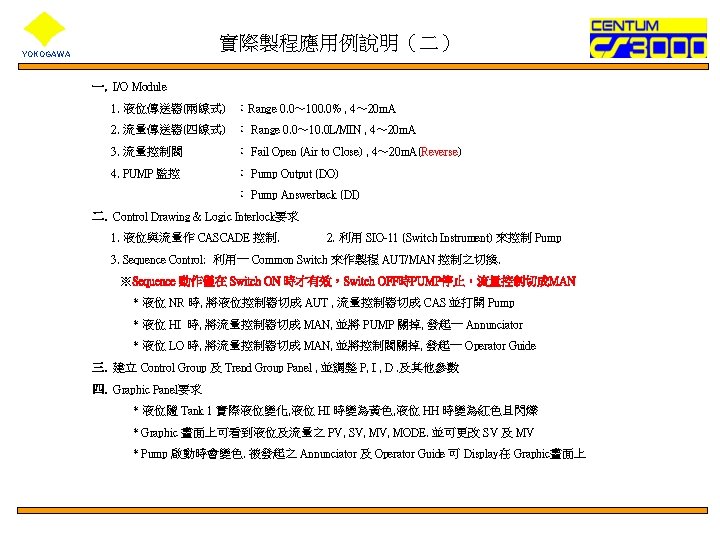
實際製程應用例說明(二) YOKOGAWA FCS 01 01 HIS 01 XX Control Hint : ◆ FCS Type : PHCD-H ◆ HIS Name : User’s HIS 01 XX ◆ Reference Station : Current Station PFCD-H (EWS獨立模擬) ◆ Control Direction : LIC_Direct ◆ Control Direction : FIC_Reverse ◆ Output Direction : Reverse ◆ Sequence Mode must be “AUT” TANK 1 I/P DP Harp Level Transmitter V 1 Hand Valve V 2 Hand Valve ADMAG(AXF Series) Magnetic Flowmeter Process Line CV 1 Instrumen t Air 空壓機 Control Valve TANK 2 PUMP
YOKOGAWA Thank you for your attention!