y rectangular waveguides TE 10 mode b z

y rectangular waveguides TE 10 mode b z 0 Ey 0 z 0 a x

y rectangular waveguides TE 10 mode b 0 z 0 y a x a x b a = 2 b z 0 b 0 0 z 0 y

y rectangular waveguides b TE 10 mode z 0 0 a a = 3 cm x

y rectangular waveguides b TE 10 mode z 0 x a 0 b wc w

y rectangular waveguides TE 10 mode b 0 z 0 a x

y rectangular waveguides TE 10 mode b 0 z 0 a x

y rectangular waveguides TE 10 mode b z 0 a 0 Ey z 0 a x g x

y rectangular waveguides TE 10 mode b z 0 0 a x

Movie to illustrate phase mixing of two propagating sinewaves in a dispersive media. b wc w

Study of an amplitude modulated pulse

Movie to illustrate the propagation of an amplitude modulated pulse in a waveguide

dispersion t 1 z t 2 z t 3 z

dispersion t 1 z t 2 z t 3 z

y rectangular waveguides TE 10 mode b z 0 0 a 8. 8. e. The transmission analogy can be applied to the transverse field components, the ratios of which are constants over guide cross sections and are given by wave impedances. A rectangular waveguide of inside dimensions [a = 4, b = 2 cm] is to propagate a TE 10 mode of frequency 5 GHz. A dielectric of constant r=3 fills the guide for z>0 with an air dielectric for z<o. x

y rectangular waveguides TE 10 mode b z 0 0 a x

y rectangular waveguides TE 10 mode b z 0 0 a x

y rectangular waveguides TE 10 mode b z 0 0 a lossy dielectric The wave will attenuate as it propagates. x

y rectangular waveguides TE 10 mode b z 0 0 Loss in walls due to finite conductivity of metal surfaces Tangential H surface current js Ohmic power loss Attenuation of the em wave a x

y rectangular waveguides TE 10 mode matching b z 0 Ey 0 z 0 a x

y rectangular waveguides 8. 8 a. For f=3 GHz, design a rectangular waveguide with copper conductor and air dielectric so that the TE 10 wave will propagate with a 30% safety factor (f = 1. 30 fc) but also so that wave type with next higher cutoff will be 30% below its cutoff frequency. b z 0 0 a a = 6. 5 cm b = 3. 85 cm x

Cylindrical Waveguides a z j


Cylindrical Waveguides a z Bessel function j
 J 1(x) 0 0 10 20")
1 J 0(x) J 1(x) 0 0 10 20
 J 1(x) 0 n is angular")
Cylindrical Waveguides a 1 j z J 0(x) J 1(x) 0 n is angular variation l is radial variation 0 10 20


Cylindrical Waveguides a z j
 J 1(x) n is angular variation l")
Cylindrical Waveguides a z 1 J 0(x) J 1(x) n is angular variation l is radial variation 0 j

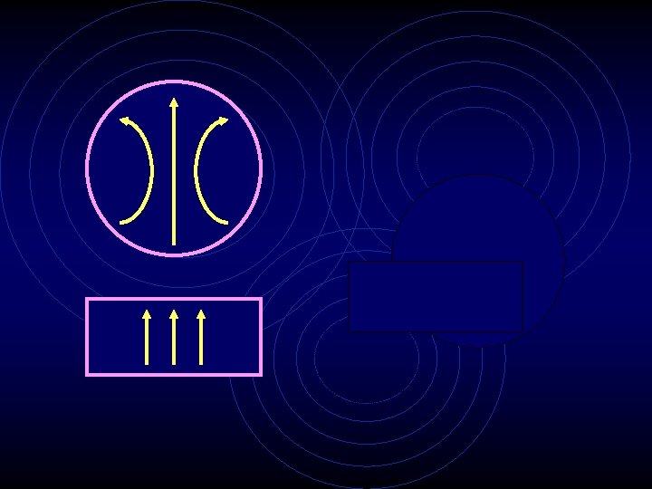
Loss decreases as frequency increases Field distribution is similar to TE 10 mode in rectangular waveguide

a v c v z 1 vg wc w j

- Slides: 34