XRay Fluorescence Spectrometry Content XRay History Who Discovered


 Sources The Coolidge Tube Radioisotopes Secondary Fluorescent Sources. synchrotron 2) Filters")
 X-ray absorption X-ray Diffraction X-ray Fluorescence Electron")


 Sources The Coolidge Tube Radioisotopes Secondary Fluorescent Sources. synchrotron 2) Filters")

 Target metal (Cu, Cr) Electrons are accelerated by")


 Sources The Coolidge Tube Radioisotopes Secondary Fluorescent Sources. synchrotron 2) Filters")

 Sources The Coolidge Tube Radioisotopes Secondary Fluorescent Sources. synchrotron 2) Filters")

 Sources The Coolidge Tube Radioisotopes Secondary Fluorescent Sources. synchrotron 2) Filters")
 photographic emulsions b) Gas-Filled Detectors c) Scintillation")
 photographic emulsions b) Gas-Filled Detectors c) Scintillation")


 photographic emulsions b) Gas-Filled Detectors c) Scintillation")

 photographic emulsions b) Gas-Filled Detectors c) Scintillation")

 Sources The Coolidge Tube Radioisotopes Secondary Fluorescent Sources. synchrotron 2) Filters")
 Energy Dispersive Systems b) Counters and Scalers")

 Energy Dispersive Systems b) Counters and Scalers")


 Handbook of Practical X-Ray Fluorescence Analysis B. Beckhoff B. Kanngie ﻙ")
- Slides: 70
X-Ray Fluorescence Spectrometry
Content : X-Ray History Who Discovered X-rays? What’s an X-Ray? How X-rays are Produced? X-Ray Generation
INSTRUMENT COMPONENTS: 1) Sources The Coolidge Tube Radioisotopes Secondary Fluorescent Sources. synchrotron 2) Filters for X-Ray Beams 3) Wavelength Dispersion with Monochromators 4) X-R. y Detectors and Signal Processors a) photographic emulsions b) Gas-Filled Detectors The Geiger Tube Proportional Counters Ionization Chambers c) Scintillation Counters d) Semiconductor Detectors 5) Signal Processes and Readout De. Vices a) Energy Dispersive Systems b) Counters and Scalers
X-Ray Methods X-ray emission (including fluorescent emission) X-ray absorption X-ray Diffraction X-ray Fluorescence Electron Microscopes X-RAY Photoelectron Spectroscopy And ……. .
X-Ray Fluorescence Spectrometry n What is it? n How does it work? n Properties n Advantages n Disadvantages
Who Discovered X-rays? n n 1895 – Wilhelm Roentgen discovered X-rays while studying luminescence produced by cathode tubes. Because he didn’t know what they where he called them X-rays (X for unknown) He also noticed that the rays caused photographic plates to darken X-ray photographs revealed the inner structure of objects
Definition : n. Basically the same thing as visible light rays n. Both are wavelike forms of electromagnetic energy carried by particles called photons n. The difference is the energy level of the individual photons - expressed as the wavelength of the rays
Radiation in the wavelength range between about 0. 1 and 25 A Clip 00
What’s an X-Ray? n n Visible light and X-ray photons are both produced by the movement of electrons in atoms Electrons occupy different energy levels (orbitals) around the atom’s nucleus When electrons drop to a lower orbital it releases energy in the form of a photon The energy of the photon depends on how far the electron dropped between orbitals.
Source of X-rays as vacancy filled by cascade of electrons from lower energy levels Clip 01
Radiation Physics n n n Ionizing radiation is radiation with enough energy to remove electrons from their orbit This causes the atom to become charged or ionized. This energy is emitted in the form of waves or particles Clip 02
Ionizing Radiation Kind Atomic Mass Electrical Charge Range in Air Range in Attenuation Body Tissue Alpha 4 +2 < inch Unable to penetrate skin Stopped by a sheet of paper or skin Beta 1/1840 -1 Several feet 1/3 inch Stopped by a thin sheet of aluminum Gamma / x-ray NA None Passes through Thick lead or steel Neutron 1 Neutral Hundreds of feet About 10% Several feet of goes through water or plastic
X-Ray and Gamma Ray Properties Charge: None Mass: None Velocity: 3 x 10⁸ m/s Origin: Gamma Rays: Nucleus X Rays: Electron Cloud & Bremsstrahlung
What are X-Rays? n n X-rays are produced when accelerated electrons interact with a target, usually a metal absorber, or with a crystalline structure. This method of xray production is known as bremsstrahlung. The bremsstrahlung produced is proportional to the square of the energy of the accelerated electrons used to produce it, and is also proportional to the atomic number (Z) of the target (absorber). Clip 03
X-rays Electromagnetic radiation Originate in energy shells of atom Produced when electrons interact with a target electron X-ray
INSTRUMENT COMPONENTS: 1) Sources The Coolidge Tube Radioisotopes Secondary Fluorescent Sources. synchrotron 2) Filters for X-Ray Beams 3) Wavelength Dispersion with Monochromators 4) X-R. y Detectors and Signal Processors a) photographic emulsions b) Gas-Filled Detectors The Geiger Tube Proportional Counters Ionization Chambers c) Scintillation Counters d) Semiconductor Detectors 5) Signal Processes and Readout De. Vices a) Energy Dispersive Systems b) Counters and Scalers
Sources The Coolidge Tube Radioisotopes Secondary Fluorescent Sources. synchrotron
X-Ray Generation X-ray tube Filament (Tungsten) Target metal (Cu, Cr) Electrons are accelerated by a potential of about 100 k Volts Schematic diagram of the Coolidge tube.
How X-rays are Produced? When fast-moving electrons slam into a metal object, X-rays are produced. The kinetic energy of the electron is transformed into electromagnetic energy. Clip 05 Clip 06
Sources The Coolidge Tube Radioisotopes Secondary Fluorescent Sources. synchrotron
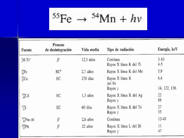
Radioisotopes A variety of radioactive substances have been employed as sources in X-ray fluorescence and absorption methods. Generally, the radioisotope is encapsulated to prevent contamination of the laboratory and shielded to absorb radiation in all but certain directions.
Radioisotopes
Sources The Coolidge Tube Radioisotopes Secondary Fluorescent Sources synchrotron
Secondary Fluorescent Sources In some applications, the fluorescence spectrum of an element that has been excited by radiation from a Coolidge tube serves as a source for absorption or fluorescence studies. This arrangement has the advantage of eliminating the continuous component emitted by a primary source.
Sources The Coolidge Tube Radioisotopes Secondary Fluorescent Sources. synchrotron
Clip 07 Clip 08
Continuous X-Ray Spectrum n n 35 ke. V electrons strike the metal target They collide with the electrons in the metal Rapid deceleration results in emissions of proton Photons with a wide range of energies are emitted because the degree of deceleration is different
Distribution of continuous radiation from an X-ray tube with a tungsten target. The numbers above the curves indicate the accelerating voltages.
Line spectrum for a tube with a molybdenum target.
Relationship between X-ray emission frequency and atomic number
INSTRUMENT COMPONENTS: 1) Sources The Coolidge Tube Radioisotopes Secondary Fluorescent Sources. synchrotron 2) Filters for X-Ray Beams 3) Wavelength Dispersion with Monochromators 4) X-R. y Detectors and Signal Processors a) photographic emulsions b) Gas-Filled Detectors The Geiger Tube Proportional Counters Ionization Chambers c) Scintillation Counters d) Semiconductor Detectors 5) Signal Processes and Readout De. Vices a) Energy Dispersive Systems b) Counters and Scalers
Use of a filter to produce monochromatic radiation.
INSTRUMENT COMPONENTS: 1) Sources The Coolidge Tube Radioisotopes Secondary Fluorescent Sources. synchrotron 2) Filters for X-Ray Beams 3) Wavelength Dispersion with Monochromators 4) X-R. y Detectors and Signal Processors a) photographic emulsions b) Gas-Filled Detectors The Geiger Tube Proportional Counters Ionization Chambers c) Scintillation Counters d) Semiconductor Detectors 5) Signal Processes and Readout De. Vices a) Energy Dispersive Systems b) Counters and Scalers
An X-ray monochromator and detector. Note that the angle of the detector with respect to the beam is twice that of the crystal face. For absorption analysis, the source is an X-ray tube and the sample is located in the beam as shown. Clip 09 For emission work, the sample becomes a fluorescent source of X-rays as shown in the insert.
INSTRUMENT COMPONENTS: 1) Sources The Coolidge Tube Radioisotopes Secondary Fluorescent Sources. synchrotron 2) Filters for X-Ray Beams 3) Wavelength Dispersion with Monochromators 4) X-R. y Detectors and Signal Processors a) photographic emulsions b) Gas-Filled Detectors The Geiger Tube Proportional Counters Ionization Chambers c) Scintillation Counters d) Semiconductor Detectors 5) Signal Processes and Readout De. Vices a) Energy Dispersive Systems b) Counters and Scalers
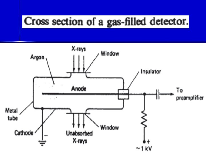
X-R. y Detectors and Signal Processors a) photographic emulsions b) Gas-Filled Detectors c) Scintillation Counters d) Semiconductor Detectors The Geiger Tube Proportional Counters Ionization Chambers
X-R. y Detectors and Signal Processors a) photographic emulsions b) Gas-Filled Detectors c) Scintillation Counters d) Semiconductor Detectors The Geiger Tube Proportional Counters Ionization Chambers
Gas-Filled Detectors n The Geiger Tube n Proportional Counters n Ionization Chambers
Gas amplification for various types of gas-filled detectors.
X-R. y Detectors and Signal Processors a) photographic emulsions b) Gas-Filled Detectors c) Scintillation Counters d) Semiconductor Detectors The Geiger Tube Proportional Counters Ionization Chambers
Scintillation counters The luminescence produced when radiation strikes a phosphor represents one of the oldest methods of detecting radioactivity and X-rays, and one of the newest as well. In its earliest application, the technique involved the manual counting of flashes that resulted when individual photons or radiochemical particles struck a zinc sulfide screen. The tedium of counting individual flashes by eye led Geiger to the development of gas-filled qetectors, which were not only more convenient and reliable, but more responsive to radiation as well. The advent of the photomultiplier tube and better phosphors, however, has reversed this trend, and scintillation counting has again become one of the important methods for radiation detection.
X-R. y Detectors and Signal Processors a) photographic emulsions b) Gas-Filled Detectors c) Scintillation Counters d) Semiconductor Detectors The Geiger Tube Proportional Counters Ionization Chambers
Vertical cross section of a lithium drifted silicon detector for X-rays and radioactive radiation.
INSTRUMENT COMPONENTS: 1) Sources The Coolidge Tube Radioisotopes Secondary Fluorescent Sources. synchrotron 2) Filters for X-Ray Beams 3) Wavelength Dispersion with Monochromators 4) X-R. y Detectors and Signal Processors a) photographic emulsions b) Gas-Filled Detectors The Geiger Tube Proportional Counters Ionization Chambers c) Scintillation Counters d) Semiconductor Detectors 5) Signal Processes and Readout De. Vices a) Energy Dispersive Systems b) Counters and Scalers
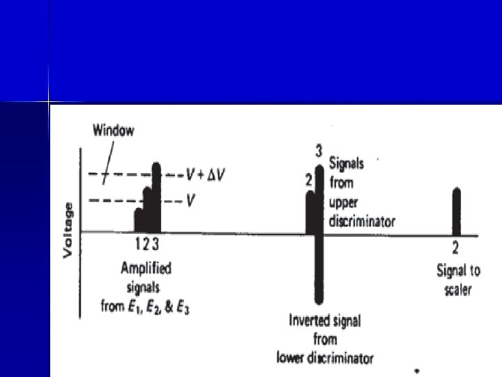
Signal Processes and Readout De. Vices a) Energy Dispersive Systems b) Counters and Scalers
Schematic diagram of a signal heigh~ analyzer. Lower plot shows he. Ight of transmitted signals upon exit from various electronic components. X-ray photons
Signal Processes and Readout De. Vices a) Energy Dispersive Systems b) Counters and Scalers
X-Ray Fluorescence Spectrometry n n n What is it? How does it work? Properties Advantages Disadvantages
X-RAY FLUORESCENCE METHODS Although it is feasible to excite an X-ray emission spectrum by incorporating the sample into the target area of an X-ray tube, the inconvenience of this technique discourages its application to many types of materials. Instead, excitation is more commonly brought about by irradiation of the sample with a beam of X-rays from a Coolidge tube or a radioactive source. Under these circumstances, the elements in the sample are excited by absorption of the primary beam and emit their own characteristic fluorescent X -rays. This procedure is thus properly called an X-ray fluorescence or emission method. X-Ray fluorescence is perhaps the most widely used of all analytical methods for the qualitative identification of elements having atomic numbers greater than oxygen (>8); in addition, it is often employed for semiquantitative or quantitative determination of these elements.
Instruments Various combinations of the instrument components discussed in the previous section lead to several recognizable types of X-ray fluorescence instruments. The three basic types are : wavelength dispersive energy dispersive And nondispersive
wavelength dispersive Instruments Wavelength dispersive instruments always employ tubes as a source because of the large energy losses suffered when an X-ray beam is collimated and dispersed into ita component wavelengths. Radioactive sources produce X-ray photons at a rate less than 10 -4 that of a Coolidge tube; the added attenuation by a monochromator would then result in a beam that was difficult or impossible to detect and measure accurately.
Wavelength dispersive instruments are of two 'types : single-channel or sequential and multichannel or simultaneous.
Multichannel instruments are widely used for the determination of several components in materials of industry such as : steel other alloys, cement, ores, and petroleum products. Both multichannel and single-channel instruments are equipped to handle samples in the form of metals, powdered solids, evaporated films, pure liquids, or solutions.
Energy dispersive Instruments
Energy dispersive X-ray fluorescence spectrometer. Excitation by X-rays from a Coolidge tube
Energy dispersive X-ray fluorescence spectrometer. Excitation by X-rays from a radioactive substance.
Nondispersive Instruments
Cutaway view ofa commercial nondispersive X-ray fluorescence instrument. (Reprinted from Amer. LDb. 6(9~ 62 (1974). Copyright 1974 by International Scientific Communications, Inc. )
Some Quantitative Applications of X -Ray Fluorescence. Clip 10 X-ray fluorescence spectrometry is perhaps the most powerful tool available to the chemist for the rapid quantitative determination of all but the lightest elements in complex samples. Clip 11 Clip 12 Clip 13 For example, Baird and Henke have demonstrated that nine elements can be determined in samples of granitic rocks in an elapsed time, including sample preparation, of about 12 min. The precision of the method is better than wet chemical analyses and averages 0. 08% relative. It is noteworthy that one of the elements analyzed is oxygen, which ordinarily can be determined by difference only.
X-Ray Fluorescence Spectrometry Advantages n n n X-ray spectra is simple and regular Matrix effect in X-ray emission are systematic, predictable and readily evaluated X-ray fluorescence spectroscopy is nondestructive.
X-Ray Fluorescence Spectrometry Disadvantages n n Small surface layer contributes to the observed X-ray line intensity Not all of the elements in a sample can be measured using the same X-ray tube, crystals, and detector
Reference : 1) Handbook of Practical X-Ray Fluorescence Analysis B. Beckhoff B. Kanngie ﻙ er N. Langhoff R. Wedell H. Wolff 2) X-Ray Analysis Ron Jenkins 3) DEAN’S ANALYTICAL CHEMISTRY HANDBOOK 4) Fundamentals of Analytical Chemistry Douglas A. Skoog & Donald M. West & F. James Holler & Stanley R. Crouch 5) Principles of instrumental analysis Skoog